In simple terms, the present invention relates to an overhead crane including a trolley and positionable hoist that eliminates side loading of the crane.
Conventional overhead cranes, this invention claims, include a frame with a pair of bridge cross members that move along a pair of main support beams. A pair of tracks are supported by the cross members and a hoist moves along the pair of tracks in a direction transverse to the main support beams.
Such a configuration does not permit the hoist to lift loads positioned outside the perimeter defined by the main support beams. Furthermore, to lift loads positioned outside the runway defined by the cross members or directly under one of the cross members, side loading of the hoist results, which is unsafe and violates regulations.

Fig 1 – a top view of a crane including a trolley and travelling hoist according to the present invention.

Fig 2 – a side view of the crane shown in Fig 1.

Fig 3 – an end view of the crane shown in Fig 1.

An overhead crane that permits positioning of the hoist directly over the load, regardless of the location of load within a crane bay, would be welcomed by users of overhead cranes.
In one embodiment, the invention provides an overhead crane adapted to be supported by first and second main support beams that are spaced apart and generally parallel.
The overhead crane includes a bridge adapted to travel along the underside of the main support beams. The bridge includes first and second girders aligned transversely to the main support beams wherein the first and second girders are spaced apart and generally parallel.
A trolley is adapted to travel along the first and second girders of the bridge; the trolley includes a rotate bearing at a bottom surface of the trolley. A rail is coupled to the rotate bearing and the rail rotates with the rotate bearing relative to the trolley. A hoist is adapted to travel along an underside of the rail with the hoist being positionable outside a perimeter defined by the main support beams.
In another embodiment, the crane includes at least one main support beam that extends between two walls of a facility and a bridge adapted to travel along at least one main support beam, including first and second girders being spaced apart and generally parallel. In this case, a trolley is adapted to travel along the bridge, and a jib rotatably coupled to a bottom surface of the trolley, including a first end and a second end.
One hoist is adapted to travel along the underside of the jib, the hoist being movable from the first end of the jib along a portion of the jib, while a second hoist is coupled to the second end of the jib and fixed relative to the jib.
Not limited
Before any embodiments of the invention are explained in detail, it is to be understood that the invention is not limited in its application to the details of construction and the arrangement of components set forth in this description or illustrated in the drawings. The invention is capable of other embodiments and of being practiced or of being carried out in various ways.
The drawings show an overhead crane (10) that positions a hoist (14) in a crane bay for lifting and unloading a load. Furthermore, the crane allows the hoist to lift a load positioned outside a perimeter (16) defined by main support beams (22, 26) of the crane.
The crane includes a bridge (18) that translates along a first main support beam (22) and a second main support beam (26). The main support beams generally extend between two walls (not shown) of a facility and are spaced apart and generally parallel to each other.
As will be readily known to those of skill in the art, the main support beams may alternatively be curved to match the inside wall contours of a round building, or include a single, curved support beam. For example, a polar crane similar to the crane shown may be used in a nuclear containment building that is built in a round configuration, in which case the main support beam(s) will be shaped in a circle instead of a straight line.
Undersides of the first and second main support beams define rails (30, 34) that the bridge, or first underrunning, travels along. The bridge travels in a substantially horizontal direction. The carriage includes a first girder (38), a second girder (42), and a pair of end trucks (46, 50) that extend between the first and second girders (38, 42). The end trucks, or U-shaped channel members, are aligned generally parallel to the main support beams.
Each end truck defines a passage (54) for receiving one of the main support beam rails (30, 34). A pair of wheels (58) is disposed in each passage (54) to facilitate travel of the bridge (18) along the rails (30, 34). A motor (62) is interconnected with each pair of wheels (58) to drive the wheels and thereby cause movement of the bridge along the main support beams.
The first and second girders (38, 42) are spaced apart from each other and generally parallel. The girders are aligned transversely to the main support beams (22, 26). A trolley (66), or second underrunning, travels along girder rails (70, 74) that are positioned on the undersides of the first and second girders (38, 42). In the illustrated embodiment, the trolley (66) travels in a substantially horizontal direction, generally parallel to the first and second girders (38, 42).
End trucks
The trolley (66) includes a pair of end trucks (78, 82) that extend from a first end (86) of the trolley to a second end (90) and are aligned generally parallel to the first and second girders.
Each end truck defines a passage (94) for receiving one of the girder rails (70, 74). A pair of wheels is disposed in each passage to facilitate travel of the trolley along the rails (70, 74).
Referring to Fig 2, first and second stop members (103, 104) are mounted to the first girder (38). The stop members prevent the trolley from travelling beyond the stop member and off the girders. In another embodiment, stop members are mounted to the second girder as well.
The jib (114), or third underrunning, includes a first end (122) and a second end (126). The first hoist (14) is mounted to the first end (122) of the jib (114) and is adapted for travel along the first end (122) of the jib (114). A bottom surface of the jib defines a rail (128) that the first hoist (122) travels along.
The first hoist includes a vertically movable load hook (130), a body (134), and an end truck (138). The end truck defines a passage (142) for receiving the jib rail (128). A pair of wheels (146) is disposed in the passage to facilitate travel of the first hoist along the jib rail. A motor (150) is interconnected with the pair of wheels (146) to drive the wheels and thereby cause movement of the first hoist (14) along the jib.
The end truck (138) is coupled to an upper surface (154) of the body (134) and the load hook (130) is supported by the body (134). In the illustrated embodiment, the first hoist is a wire rope hoist. In another embodiment, the first hoist includes other configurations for lifting, as will also be readily apparent to those of skill in the art.
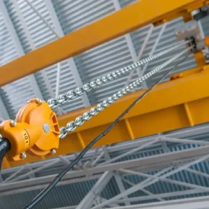
A second hoist (158) is attached to the second end (126) of the jib (114). In the illustrated embodiment, the second hoist (158) is a chain hoist and fixed relative to the jib (114) to provide up-ending and down-ending materials.
The second hoist (158) includes a vertically movable load hook (162) and is articulated to rotate within a plane defined by the jib (114). In a further embodiment of the crane, a second hoist at an opposite end of the jib from the first hoist is not necessary.
Side loading results when using an overhead crane without the rotatable jib (114) and the travelling first hoist, to lift loads positioned outside the main support beams (22, 26), or directly under the first and second girders (38, 42). For loads that need to be up- or down-ended, both hoists (for example, the first hoist and the second, counter-balance hoist) are used, however, the two hoists are typically up to 11ft apart.
This creates a condition where one or both of the hoists are side loaded, that is to say one hoist is more severely loaded than the other hoist. Furthermore, lifting loads positioned outside the main support beams (22, 26) and/or directly wider of the first and second girders (38, 42) results in the hoist side pulling (for example, the hoist acting horizontally rather than vertically) to pick and lift the load because the hoist cannot be positioned directly over the load.
About the application
United States patent application number 20090159548 was filed on June 25 2009 by Steven K. Waisanen.
Disclaimer
As edited versions of the originals, this article and accompanying drawings may omit legally or technically important detail.