The structures associated with blocks and hoists, including crane bridges and gantries, are generally robust and unlikely to deteriorate much from natural causes in the short term. However, there are problems which can arise that have serious consequences. As a result, lifting structures should always be included in the in-service inspection regime.
Generally, the structures associated with lifting equipment fall into two categories. The first includes those which are dedicated solely to the lifting application. The second encompasses those which have other functions, typically as the structural elements of a building. In the latter case, it is customary to consider the lifting equipment as starting where the connection is made to the building. For example, if a runway track is supported by the roof trusses, the track is regarded as lifting equipment but the roof trusses are not. Clearly they nevertheless have to be strong enough for the application in question, so normal good practice is for the supplier of the lifting equipment to provide details of the loadings it will impose on the building. A suitably qualified consulting engineer or architect is then called upon to verify that the building can take those loads. The same principle applies for equipment such as gantries and swing jibs which are supported by any other primary structure.
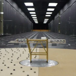
Herein lies the first potential problem because, over time, changes can occur which affect the primary structure. These changes may include the need to support additional equipment, pipe work or water tanks, as well as subsidence or accidental damage. All can adversely affect the lifting equipment. A simple runway can develop a slope, a slewing jib can tend to slew to one side, a crane gantry can go out of span and cause the crane to bind on or climb the track. Such misalignments also place undue stress onto the connections which are usually bolted or clipped and increase the wear on tracks and wheel flanges.
Inspecting structural elements
As usual, it helps to be methodical. Check the following:
• Look for any changes that might affect the primary structure.
• Where possible, visually check alignments.
• Operate the equipment and look for symptoms of misalignment.
• Check connections for signs of looseness or movement.
In the case of structural elements which are solely for the lifting application, short term problems usually arise as a result of misuse or accidental damage rather than wear. Perhaps the most obvious misuse is a straightforward overload. Unless fitted with a load limiter, most lifting machines can impose sufficient overload to permanently deform a structure with the same working load. However, the way the equipment is used can also overload the structure even within the working load.
Dragging loads is a common misuse. On a runway, dragging from the side causes the trolley to tip and transmit the load through the wheels on one side only. This results in local deformation of the runway flange and also, possibly, the trolley. Dragging from the end of a runway imposes excessive loads on the end stops and supporting structure. On a slewing jib, dragging from outside the jib’s arc effectively increases the radius and consequently all the forces imposed on the jib and its connections or foundations. Dragging loads with an overhead crane can cause a variety of problems similar to the above depending on position and direction; as with all abuse, it is better to stop it than to try and detect and remedy the consequences.
Collision damage can occur if the lifting machine hits the end stops at speed or under power. Modern overhead cranes are often, if not usually, fitted with equipment to prevent collision between cranes on the same track and between the crane and the end stops. Older cranes often lack such safeguards. Such collisions impose a very high shock load onto the gantry structure and can cause bolts to shear, welds to crack and connections to deform. If the gantry is supported by, or braced by, the building, it in turn can be weakened. Runways and slewing jibs rarely have anything other than physical end stops and rely on operator care.
Collision damage can also arise from careless driving of delivery vehicles, forklift trucks and the like. Other problems can arise from the environment. Corrosion or the build up of dirt or other debris on track running surfaces can result in lack of traction or erratic movement.
Lifting structures such as crane bridges, slewing jibs and runways normally display the working load in large characters which should be clearly visible from the floor. The value displayed should be clear and not conflict with the working load of the lifting machine.
In all cases when inspecting structural elements dedicated to lifting applications, look for:
• Signs of overload indicated by permanent deformation.
• Signs of misuse indicated by local deformation of runway flanges, end stops and supporting structure.
• Signs of collision damage such as deformed connections, sheared bolts and cracked welds.
• Security of foundation bolts at the base plates of structures such as pillar type slewing jibs or independent runway or gantry structures.
• Security of all connections.
• Presence and effectiveness of end stops.
• Debris etc on track running surfaces.
• Working load marking which should be clearly visible and not conflict with that of the lifting machine.
Power feeds
Whilst inspecting the structural elements of lifting equipment, any power feed system should also be checked. The various enclosed conductor systems used on cranes and long runways are unlikely to be a problem unless there are signs of physical damage to the conductors, their supporting brackets or the collectors and their bracket. However, a functional test of travelling the full length of the track will enable the inspector to observe any problems.
Other forms of electrical power feed involve some form of cable, either close coiled or festooned, or from a cable reeling drum. In all cases, the power should be isolated and the cable checked for damage, particularly at the glands and points where it is clamped or flexes. Check also for the security of any fixings and that any sags or loops in the cable cannot foul on anything in their path. Check that the lifting machine can satisfactorily travel the full length of the track. With cable reeling drums in particular, there is often a fine balance between having sufficient tension to control the sag without pulling the trolley back.
The supply to pneumatic hoists is inevitably via a hose, either close coiled or festooned, and these should be checked for wear and security in a similar way to their electrical counterparts. Usually there is an air filter and lubricator located close to the pneumatic hoist and these should also be checked and maintained in serviceable condition.
When inspecting the power feed system, in all cases:
• Isolate the power feed system before work commences.
• Check for physical damage to the system, its supporting brackets, track etc.
• Check cables for security and damage, particularly at glands and at points where it is clamped or flexes.
• Check that sags or festoon loops cannot foul anything in their path.
• Check tension in cable reeling drums.
• If the above checks prove satisfactory, reconnect the power and make a functional test of travelling the lifting machine along the full length of the track.
In-service inspection saves money and time. Neglected and abused lifting equipment is, at best, an unnecessary drain on resources leading to costly repairs or prematurely ending the life of the equipment. At worst it poses a direct threat to health and safety. A little time wisely invested at regular intervals resolves both these issues.
picture caption:
Subsidence in a factory’s foundations can affect cranes tied into the structure