Performing operations on a wind turbine
5 August 2010A method for performing operations on a wind turbine that involve handling heavy parts has been granted a US Patent.
There remains a need for a system for handling heavy parts of wind turbines that is cost effective and, at the same time, retains the flexibility of the terrestrial and marine cranes.
Summary
The present invention provides a method for performing operations on a wind turbine that involve handling the heavy parts on the wind turbine. There is further provided a system including a hoist and a winch suitable for carrying out the method. A nacelle frame assembly is also provided for a wind turbine according to the invention. This first hoist is lightweight, and it can raise parts of the order of 1,000kg.
The method of the invention comprises the processes of hoisting a second hoist on the nacelle frame by using the first hoist. This second hoist is more powerful than the first hoist, capable of raising parts up to 9,000kg.
According to one embodiment of the method of the invention, a further process is carried out before removing the second hoist from the nacelle frame. This process preferably comprises hoisting a crane and removably mounting the crane on the nacelle frame of the wind turbine.
Specifically, the crane is mounted on the nacelle frame at a rear portion thereof, opposite the portion of the frame where the wind blades of the generator are arranged.
This crane is arranged to cooperate with the second hoist, and they are used for raising and lowering a winch in a further process of the procedure of the invention. In some embodiments, the winch is provided with a coupling structure for attachment to the nacelle frame.
The winch subsequently is removably mounted on the nacelle frame of the wind turbine, particularly at the rear portion thereof.
Nacelle frame
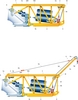
A nacelle frame (1) is shown having a front portion (A) where the wind blades of the wind turbine (not shown) are arranged, and a rear portion (B) opposite the front portion (A).
The nacelle frame is formed with a metal structure having upper section members or rails (1a) and lower section members (1b). A lower opening (2) is formed in the lower section member (1b) so that at least some of the heavy parts (100, 200, etc) of the wind turbine can be passed through the structure of the nacelle frame (1).
A first, lightweight hoist (3) is substantially permanently mounted on an upper portion of the nacelle frame (1) by means of a carriage (3a). Preferably, hoist 3 is movable, preferably either on one or more wheels, such as 8, and or one or more rails, such as 1c.
The first hoist (3) may be moved sideways in the carriage (3a), and the carriage (3a) maybe moved lengthways along the upper portion of the nacelle frame (1), that is, in a horizontal direction that is perpendicular to the direction in which the devices are lifted from the ground so that it may be positioned substantially aligned above the opening (2) of the nacelle frame (1).
The first hoist (3) is provided with cable (3b), and it is capable of raising parts on the order of 1,000kg.
A second hoist (4) is further provided. This second hoist (4) is more powerful than the first hoist, and it is capable of raising heavier parts, as discussed. The cable (3b) in the first hoist is suitable for hoisting the second hoist (4). The second hoist (4) is removably mounted to rear portion B of the nacelle frame of the wind turbine. The second hoist (4) comprises a drive chain (6d).
Crane
A crane (6, Figure 5) is further provided at the rear portion (B) of the nacelle frame (1). The crane has a tension wire (6a), one end of which is connected to the front portion (A) of the nacelle frame. The tension wire (6a) is provided with tensioner 6b, such as, for example, a tooth and pawl mechanism for adjusting tension in the tension wire (6a).
The crane further includes a crane arm (6c) mounted on the rear portion of the nacelle frame, and it carries the chain (6d) of the second hoist (4) running between pulleys 6e, 6f. One end (6g) of the chain (6d) is adapted for hoisting a winch (5b), the other end (6h) thereof being connected to the second hoist (4).
The winch (5b) has a still higher weight capacity, such as on the order of 30,000kg. It is movable, preferably utilising one or more wheels, such as 9, and/or one or more rails, such as 1a.
It comprises a carriage structure (5a) adapted for being attached to the rear portion (B) of the nacelle frame (1), and a wire rope reel (5b) for hoisting the parts 100, 200. Winch 5b, carriage 5a, and coupling structures 5c and 5d form a winch assembly (5).
The winch 5b preferably is adapted for being moved along the rails (1a) of the nacelle frame. The coupling structures (5c and 5d) facilitate the coupling of the winch to the nacelle frame in a manner that facilitates its movement onto the rails (1a).
Lowering
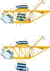
For lowering, for example, the generator (100) from the nacelle frame (1) according to the method of the invention, the first hoist (3) hoists the second hoist (4, see Figure 2) and the crane (6) from the workplace ground.
Both the second hoist (4) and the crane (6) are mounted at the rear portion (B) of the nacelle frame (1, see Figures 4 and 5). In this regard, the second hoist is passed through the frame opening (2) and then moved to the rear portion (B) of the nacelle frame (1).
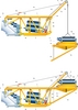
The crane (6), cooperating with the second hoist, hoists the winch assembly (5, see Figure 6) to the nacelle frame until the coupling structure, preferably comprising two connecting arms (5c, 5d) of the winch assembly (5), face the rear portion (B) of the structure of the nacelle frame (1, see Figure 7).
The carriage structure (5a) of the winch assembly (5) then becomes removably attached to this rear portion (B) of the nacelle frame (1). It is to be noted that in other embodiments of the method herein described according to the invention the winch assembly (5) is directly hoisted by the second power hoist (4) to the nacelle frame (1).
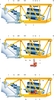
Once the winch (5b) has been already removably mounted to the frame rear portion (B), it is disengaged from its coupling structures (5c, 5d) and moved over the upper section members (1a) from the rear portion (B) to the front portion (A) of the nacelle frame until it becomes substantially aligned with the opening (2) as shown in Figure 8.
The generator (100) can be coupled to one end of the wire rope (5e) of the winch (5b) and it is lowered to the ground so that a new or repaired generator (100) is hoisted again to the nacelle frame (1), as shown in Figure 9.
Once the new or repaired generator has been fitted in the wind turbine, the winch assembly (5), the second hoist (4) and the crane (6) are disconnected from the nacelle frame and lowered from the nacelle frame.

Figure 1 is an elevational view of the preferred embodiment of a nacelle frame with a first hoist and exemplary heavy parts of a wind turbine therein which are to be repaired or replaced; Figure 2 is an elevational view of the nacelle frame of Figure 1 showing a second hoist being lifted by the first hoist; Figure 3 is an elevational view of the nacelle frame of Figure 1 showing the second hoist lifted to the nacelle frame.

Figure 4 is an elevational view of the nacelle frame of Figure 1 showing the second hoist lifted being moved to a working position on the frame; Figure 5 is an elevational view of the nacelle frame of Figure 1 showing a crane mounted at a working position on the frame.
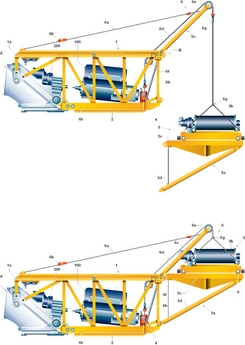
Figure 6 is an elevational view of the nacelle frame of Figure 1 showing the crane lifting a winch assembly; Figure 7 is an elevational view of the nacelle frame of Figure 1 showing the winch assembly secured to the nacelle frame.

Figure 8 is an elevational view of the nacelle frame of Figure 1 showing the winch moved to a working position; Figure 9 is an elevational view of the nacelle frame of Figure 1 showing the winch lifting a heavy portion of the turbine.
About the patent
Pere Viladomiu i Guarro and Sebastian Valero Lafuente (both Barcelona, Spain) were awarded US Patent 7,735,808 on June 15, 2010. Application number 11/638,863 was filed on December 14, 2006. The assignee is Ecotecnia S. Coop. CL (also of Barcelona).
Disclaimer
As edited versions of the originals, this article and accompanying drawings may omit legally or technically important detail.