
The hoist has a line of chain or wire rope. There is at least one gear (20) mechanically coupling the hoist driver and drum, also rotating about the gear axis x-x. There is one proximity switch supported by the frame and adjacent to the face of the gear so that the rotating face moves relative to the proximity switch. There is also a second proximity switch similarly mounted. These two switches are configured to sense the presence or absence of the face, and are linked with a controller (Fig 4 – 29). So the proximity switches, control unit and hoist driver are configured to prevent the hoist drum from rotating in the upward direction according to the signals from the proximity switches, and also the downward direction.
Prior art
Hoists often include travel limiting devices to ensure safety, particularly when lifting or lowering heavy objects. These are intended to prevent damage or dislodgment of the load, or damage to the hoist if the load is attempted to be lifted too far. Similarly, operating the hoist too far in a downward direction could also be desirable.
Some of the previous developments to this end and their drawbacks are as follows:
US Patent 7,097,155 uses optical sensors to detect a present minimum number of windings on the drum. If this limit is reached an alarm is activated. The inventors say that an optical sensor working off the number of drum windings does not have application across a broad number of hoists.
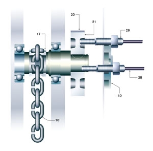
Fig 1 – Schematic representation of one embodiment of a system for controlling an overhead crane
US Patent 6,966,544 also keys off the windings on the drum but with a proximity limit switch to sense the presence or absence of wire rope around the drum. The inventors say that this type of configuration is difficult to adjust depending on the desired limits, and also requires a winding drum.
Paddle type or block operated limit switches with mechanical actuators are not normally considered adjustable.
A geared limit switch, typically driven by the hoist shaft, operates by counting the number of revolutions of the hoist drum. When the threshold is met a cam or gear actuates a microswitch and power is cut. The geared limit switch can be fitted with different gear ratios to accommodate various lift ranges. The adjustment becomes more sensitive as the gear ratio becomes numerically higher.
A screw-type limit switch has a fine-threaded shaft with a pair of nuts travelling along its length. A microswitch near each end of the shaft provides the limits. The nuts can be adjusted but the length of the shaft limits the device.
Thus the new development, say the inventors, is beneficial in providing a limiting device that has set points that are easily adjustable and can be used with hoists having non-winding drums or sprockets.
Description
The objectives of the invention include the provision of a hoist in which the upper and lower limit of travel can be set and be entirely adjustable electronically. The limits are triggered by rotation in the gear train. Another objective is to provide a hoist that limits the upper and lower vertical travel of the loads using slots or bosses in a rotating component of the hoist’s gear train. The limit switches may be independent of the hoist’s available lift.
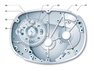
Fig 2 – Partial vertical sectional view of the hoist
The control system of the invention may have a user interface (Fig 4 – 39) by which the upper and lower limits of rotation of the hoist drum can be easily adjusted.
In Figs 1 and 2, the preferred embodiment, the hoist includes a conventional frame or housing, a load-bearing chain (18) extending over a drum or sprocket, a motor (17) for selectively rotating the drum, a ear train between the motor and drum, and an AC motor brake.
The conventional motor has one or more speeds with a standard contactor control between the power supply (Fig 4 – 48) and motor to power and control the motor direction. The ‘up’ contactor and coil (46) powers the motor in an upward direction with the ‘down’ contactor and coil (47) doing the opposite. In the event of a power cut the brake (34) automatically sets.
Other types of drums may be used, such as a conventional drum around which the wire rope of a winch is wound-on or wound-off, thus the term ‘drum’ includes sprockets.
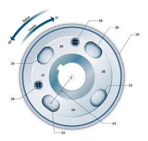
Fig 3 – One of four diagrams in the patent showing the relative orientation of the gear end face and proximity switches, shown here in the first rotational position
The hoist includes a conventional forged gear train between the drum and motor to couple them and transfer the torque and speed of the motor to a torque and speed that can be utilised to drive the hoist drum. The patent also covers other gear arrangements and ratios such as a billet gear.
A sprocket gear (20) rotates with the drum or sprocket about the axis x-x. Shown in Fig 1 it has a right-facing face (21) rotating with the drum as in conventional hoists.
The preferred embodiment of the limiting system of the invention includes two proximity switches (26 and 28) supported so that their sensing ends are adjacent to the rotating face (21) of the gear. The proximity switches communicate with the controller as part of the hoist’s control circuit in Fig 4. The user interface has set buttons 44 and 45. The conventional proximity switches are capable of sensing the presence or absence of an object or surface within one or two millimeters of the sensing end without touching the surface. A cited suitable type is the model E57-08GU02-C from Cutler-Hammer.
The mounting bracket (40) holds the proximity switches close to the gear face and positioned adjacent at the same radius (42) from the x-x axis to sense the same annular portion of the face as it rotates. They are positioned so as not to be at right angles to each other – actually at 109 degrees apart in the preferred embodiment.
The proximity switches provide either an ‘on’ signal or an ‘off’ signal to the controller. The first indicates the presence of an object whilst the latter indicates its absence. The gear face includes an annular portion (41) that rotates at roughly the same axial radius as the proximity switches. The annular portion has an alternating series of positive areas (Fig 3 – 35-38) and negative areas (22-25). The annular portion of the face and the proximity switches are configured and orientated so that when the positive areas rotate by the adjacent switches they register an ‘on’ signal. Similarly, when the negative areas pass by the proximity switches, they register an ‘off’ signal. In the preferred embodiment there are four elongated slots at right angles to each other about the x-x axis to form the negative areas.
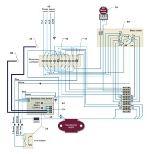
Fig 4 – Schematic electronic diagram for the hoist control
The orientation of the switches relative to the slots will result in the proximity switches sending a sequence of signals to the gear during rotation of the gear. The rotation of the face in a counterclockwise direction correlates to the drum moving in a downward direction with the load moving away, and vice versa. Since the slots 22-25 are orientated at right angles, but the proximity switches are not, the switches send a different sequence of signals to the control unit depending on whether the face is moving to wind up or down. The slots are elongated with opposed parallel surfaces with semicircular ends with a radius the same or larger than the radius of the ends of the switches. The slots are thus longer than the diameter of the sensing ends of the proximity switches.
Fig 3 shows a first signal count of ‘on-on’ with switch 26 registering an ‘on’ signal as it senses a positive surface, as does switch 28. As the face moves counter-clockwise, the leading edge of slot 22 passes in front of switch 26, so that the switch changes its signal from ‘on’ to ‘off’. At the same time switch 28 will still be sending an ‘on’ signal, giving a count of ‘off-on’. Similarly the count changes another twice with continued upward drum rotation as shown in Table 1:
Table 1: Raising switching sequence
Switch 26: On, Off, Off, On; Switch 28: On, On, Off, Off
If the drum and face are moving in the downward or clockwise direction the sequence will differ. Thus, starting from the Fig 3 position, the first signal is again ‘on-on’ but then switch 26 will still be sensing the presence of surface 38 when proximity switch senses the absence of surface 37 as the leading edge of slot 24 passes by proximity switch 28 to result in an ‘on-off’ signal. The signals change again with continued movement as shown in Table 2:
Table 2: Lowering switching sequence
Switch 26: On, on, off, off; Switch 28: On, Off, Off, On
Thus the system is able to determine from the sequence of signal which way the drum and chain or wire rope are moving. The preferred embodiment also provides a check of location when the hoist is turned off and then turned back on.
Some account for ‘play’ in the gears. If the reading when the hoist is turned back on has changed to ‘on-off’, the control knows that the drum has rotated on count down, or if the count is now ‘off-on’, control knows that the system has rotated one count up. However, if the control registers ‘off-off’, it is not able to determine whether the gears have rotated two counts up or down, and thus the hoist is immediately shut off until recalibrated.
The control’s user interface allows for the hoist’s upper and lower limit to be easily adjusted without reference to the total travel of the hoist or requiring mechanical adjustment of the switches. The up-set button (44) and down-set button (45) are included on the interface, together with a conventional panel or remote pad for
user hoist movement. The upper and lower limits can be set by running the hoist between the desired upper and lower limit and using the system to count and store the number of sequence changes between those limits, thereby calibrating the travel limits and setting a reference sequence and count for the permitted travel of the chain or wire rope.
To set the upper and lower limits the user pushes both the up-set and down-set buttons simultaneously to send a signal to the control to both zero and temporarily inactivate the sequence counter. The hoist is operated so the load-bearing end is at the desired upper or lower limit, and either the up-set or down-set button pressed accordingly. If the count and sequence of signals between these two positions is exceeded, the control disconnects the power from the motor and sets the brake.
About the patent
This article is an edited version of US Patent 7,284,743 published on October 23 2007 from an application filed November 3 2006. The inventors are James J Brighton, Samuel J Darling and Phillip W Kary, all of Michigan, US. The patent is assigned to the Columbus McKinnon Corp. of Amherst, New York State.
Market status
The patent assignee, the Columbus McKinnon Corporation, is the parent company of several hoist-manufacturing divisions including CM Industrial Products, Yale Hoist, Coffing Hoist and Budgit. Budgit (Lift-Tech Intentional) is actively marketing the invention on its electric hoists based on easy adjustability at the touch of a button. The range covers capacities 0.5-3 US tons with a standard lift of 10 feet. The hoists also have a new heavy-duty motor brake of the AC spring set disc type, with one-step adjustment. The limiting system development can be used on several other models available from group companies.
Disclaimer
As an edited version of the original patent, this article may omit legally or technically important text or detail.


