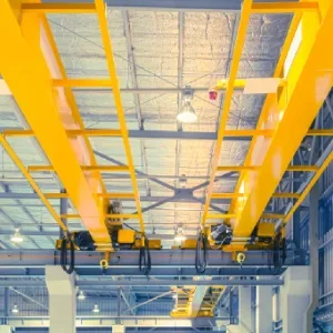
An overhead travelling crane comprises a hoisting mechanism mounted in a cross travel crab or trolley supported by the crane bridge. The crane bridge is in turn supported by the end carriages which run on the down shop gantry or track. The crane therefore provides motion on all three axes, with minimal obstruction of the floor space below.
Within this simple configuration, there are many variations. Each has advantages and disadvantages, depending on the application. The main variations cover whether the end carriages run on top of the gantry rail or are suspended beneath a track, whether the bridge is single girder or a double girder and whether the travel motions are manual or powered. Each of these variations ultimately limits the capacity of the crane, its functionality, the height of lift and the area it can serve.
If the crane is part of a completely new project, matters such as height of lift and the area it serves can be addressed in the overall design. However, the more likely scenario is an existing building into which the user is trying to fit the best compromise within a limited budget.
The starting point is often dictated by the availability of a supporting structure. For the time being, let us assume that there is an existing gantry of adequate capacity and consider the possibilities for a top running crane.
The key dimensions arising from the gantry will already be fixed. These are the height from the floor to the gantry rail, the height above the rail, the distance from the centre of the rail to the nearest point at the side of the building and the span between the rail centres.
To get the maximum height of lift, the hoist mechanism is usually positioned as high as possible just below the roof structure. If the roof is of a traditional triangular truss design, then the same height is available across the whole span. If it is a portal frame type, then more height is available at the centre of the span, but at the cost of a loss of access to the sides of the building.
With a top running crane there will always be some space to the sides of the building which cannot be accessed. The same is true at the ends of the building.
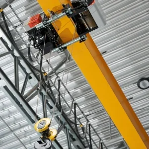
To position the hoist mechanism as high as possible also usually means a double girder bridge; with a single girder bridge, there is the depth of the girder to be accommodated as well as any height taken up by the cross travel trolley. However, the height of lift obtained by a double girder bridge may not all be useable because, at maximum height, the hook is up between the girders.
If the load to be lifted is wide or a lifting beam is involved, then they may foul the underside of the bridge girders before the hook is fully raised. The longer the span, the deeper the girders and the worse this effect will be. Specialist manufacturers can resolve this problem by positioning the rails for the crab between the girders instead of on top of the girders.
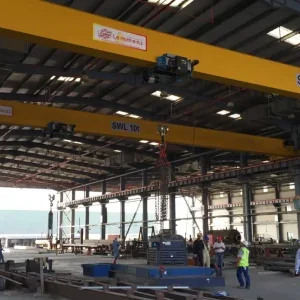
For cranes of moderate capacity, span and duty cycle, if the height of lift is not an issue, then the solution is usually a single girder crane.
For both single and double girder cranes, if the height above the gantry rail is insufficient to accommodate the end carriage and the bridge girder (and for double girder cranes also the crab) then the connection between the end carriage and the bridge girder can be cut down or made flush. In other words, instead of the girder sitting on top of the end carriage it is notched out so that it connects partially or fully onto the side of the end carriage.
Let us now consider the options for underslung cranes. These are popular, particularly for the lower capacity applications. Traditionally they comprise a bridge and end carriages, which run on the bottom flange of rolled steel joist or universal beam tracks. The tracks are often supported by the roof of the building or by independent goal post frames. Although double girder design is possible, most have a single girder bridge fixed to the underside of the end carriage.
This has the advantage of allowing the lifting machine to cross the bridge and pass under the track, reducing to a minimum the dead space at the side of the building.
It also means that the bridge can be supported by more than two tracks, thereby covering a much wider span without the considerable increase in section of beam, and weight. Moreover, by incorporating a latching mechanism into the end of the bridge girder, it enables the crane to link up with a fixed runway leading to an adjoining workshop bay and even other cranes.
Underslung cranes of this traditional type are still available. However, several manufacturers offer cranes that utilise special track sections and a range of standard components.
One of the features of these types of underslung cranes is the method of connecting the bridge to the end carriage. Traditional crane design uses a rigid connection and, to ensure that the crane can travel down shop smoothly and without crabbing, there is a minimum end carriage length relative to the crane span.
BS 466 requires a minimum of 1/7th span, or 1/8th for underslung cranes with a lower travel speed. Even on a short span crane, this can leave an area at the ends of the gantry which cannot be reached by the hook.
In contrast, the ‘track system’ type of crane has a pivot connection between the bridge and the relatively short trolley type end carriage. When travelling, the crane articulates and, effectively, one end carriage leads and the other is towed. This design minimises the area which cannot be reached at the end of the tracks and enables push (manual) travel to be used for lower capacity cranes.
Whichever type of overhead crane can be accommodated by the restrictions of the building, several other related matters must be given some consideration.
The first is the duty cycle it will be required to operate. From the point of view of the structural elements of the crane, this means estimating the average loads relative to the maximum capacity and also the number or frequency of lifts.
The method of travel must also be considered. The options are:
• ï„·Push travel. This is only suitable for lower capacity cranes where the bridge is not too high, otherwise it will tend to lag then snatch.
• ï„·Hand operated, by means of a hand chain. This can be advantageous if precision positioning is required.
• Power operated.
If precision positioning of the load is required then, just like a slewing jib, a light duty overhead crane is generally more flexible than a heavy duty crane and a bouncy crane is not as user friendly as a stiffer crane.