

Each beam of a gantry crane supports a main hoist and an auxiliary hoist. Both the main hoist and the auxiliary hoist are coupled to the beam by a trolley assembly for effecting lateral movement of the hoist along the beam. Precise positioning of the hoists is important in many lifting applications.
The gantry crane can be configured or utilised in a panel turner application wherein a lift assembly is operably attached to the gantry structure and is designed to lift and manipulate, for example, large prestressed concrete slabs or panels that may weigh many tonnes apiece. While panel turners for gantry cranes provide a number of advantageous features, they nevertheless have certain limitations.
Improved features
The present invention provides improved features for a lifting mechanism utilised in a crane. Specifically, according to a preferred aspect of the invention, the improved features are applicable for use with a panel turner for a gantry crane.
According to one aspect of the invention, a gantry crane has a gantry structure including a first horizontal beam and a second horizontal beam, and lift mechanisms secured to those horizontal beams.
The lift mechanisms can include hoist mechanisms (sometimes referred to simply as hoists) and trolley assemblies for lateral movement on the horizontal beams. Typically, a gantry crane will include a main hoist trolley and an auxiliary hoist trolley on each beam, which are controlled by an hydraulic system.
The hydraulic system of the present invention is configured to reduce the hoist capacity (for example, the lifting capacity) of the main hoist trolleys to protect the overhead horizontal beams from being overloaded. This is done when it is necessary to use both the main hoist and the auxiliary hoist to lift a load.
In situations that require use of the main hoist trolley and the auxiliary hoist trolley, the hydraulic system of the gantry crane of the present invention is configured to reduce the main hoist capacity to a lesser amount.
Load engagement
The hoist mechanisms each include a load engagement member. The load engagement member can be, for example, in the form of a hook or other similar structure for connecting the hoist mechanism to the load.
The load lifting assembly can further comprise a second horizontal beam spaced apart from the first horizontal beam, such as in a gantry crane. The second horizontal beam can include a second main hoist mechanism and a second auxiliary hoist mechanism coupled to the second horizontal beam.
The hydraulic circuit is configured to also operate the second main hoist mechanism coupled to the second horizontal beam. Specifically, the main hoist directional control valve includes a first output control line to control the hoist motor of the first main hoist mechanism, and a second output control line to control the hoist motor of the second main hoist mechanism.
A method of lifting a load using a load lifting assembly having a load support structure with a set lift capacity, without exceeding the lift capacity of the load support structure is provided.
The method includes selecting both the main hoist mechanism and the auxiliary hoist mechanism to lift the load and reduces the ability of the main hoist mechanism to a reduced second weight capacity wherein the reduced second weight capacity and the third weight capacity are collectively not greater than the first weight capacity.
After reducing the capacity of the first main hoist mechanism, the method then provides for lifting the load with the first main hoist mechanism at the reduced second weight capacity and the first auxiliary hoist mechanism. The method further includes providing a hydraulic system to operate the first main hoist mechanism.
Lifting beam
A load lifting assembly comprises a load lifting support structure including a first horizontal beam and a second horizontal beam spaced apart from the first horizontal beam, a first main hoist mechanism coupled to the first horizontal beam, a second main hoist mechanism coupled to the second horizontal beam, a first hydraulic circuit configured to operate the first hoist mechanism, and a second hydraulic circuit configured to operate the second hoist mechanism.
The assembly further includes a first equalisation valve system configured to connect the first hydraulic circuit and the second hydraulic circuit to a common hydraulic line when energised. In some instances, two or more equalisation valves can be utilised in the system.
The equalisation valve system is energised when both the first hoist mechanism and the second hoist mechanism are utilised together to lift a load. The first and second hoist mechanisms can be the main hoist mechanisms of the first and second cross-beams of a gantry crane, or the auxiliary hoist mechanisms utilising a second equalization valve system to couple the auxiliary hoist mechanisms to a common line.
The load lifting assembly further comprises a control element having a first control position to allow for independent operation of the first hydraulic circuit and the second hydraulic circuit, and a second control position for energising the equalisation valve(s). The control element can include one or more joysticks, for example. The assembly can be used to lift and turn a panel.
Additional structure
The gantry crane can include an additional structure. For example, the first side support frame can include a front leg and the second side support frame can include a front leg, wherein the first end of the first cross-beam is connected to the front leg of the first side support frame and the second end of the first cross-beam is connected to the front leg of the second side support frame.
Similarly, the first side support frame can include a rear leg and the second side support frame can include a rear leg, wherein the first end of the second cross-beam is connected to the rear leg of the first side support frame and the second end of the first cross-beam is connected to the rear leg of the second side support frame.
Additionally, the front leg and the rear leg of the first side support frame and the second side support frame can each be connected by a respective lower side beam and an upper side beam.
Technical illustrations
Figure 1 is a prior art schematic of a rubber-tyred gantry (RTG) crane power system. Prime power is provided by a diesel genset (101) which is comprised of a diesel engine (102) and an alternator (103), which converts mechanical power from the engine (102) to AC electrical power.
AC power is available for the crane’s auxiliary power systems (106) and is converted by rectifier (104) to DC power supplied to a DC bus (105) for distribution to operate electric motors (107) for propelling the crane and to carry out other crane operations such as traversing, and lifting and lowering.
The crane may also have a dynamic brake capability (108), which allows the motors (107) to act as electrical generators providing a braking force while lowering a load. The electrical energy generated by the dynamic braking system (108) is typically dissipated in a resistive grid (not shown).
Figure 2a and b is a schematic view showing a hybrid RTG crane loading a container on a truck.
Figure 3a, b and c is a side schematic view showing various possible locations for a prime power source and energy storage system for a hybrid RTG crane. In Figure 3a the lower components of an RTG crane is shown with legs (601) and electrical control panel (602). Figure 3a shows a power pack (603) comprised of, for example, an engine and a battery pack installed under the main transversal beam of the RTG.
Figure 3b shows a power pack comprised of, for example, an engine (605) and a battery pack (604) where the engine (605) is installed under the main transversal beam of the RTG and the battery pack (604) is installed along the main transversal beam of the RTG.
Figure 3c shows a power pack separated into two modules (606 and 607) with the modules installed under each side of the main transversal beam of the RTG. The module (606) may be, for example, a battery pack and the module (607) may be, for example, an engine.
Figure 4 is a block schematic of the elements of a multi-engine and multi-energy storage configuration for a hybrid crane power system. The principal elements of the power supply system are two engine systems each comprised of engine (903), alternator (904) and rectifiers (905), and energy storage systems such as, for example, a battery pack (931) and capacitor bank (933), all of which are shown connected in parallel to a DC bus with a positive side (901) and a negative side (902).
Buck-boost circuits (932) and (934), for example, can be interposed between the DC bus and energy storage systems to allow independent control of the voltage on the DC bus. For example, the capacitor bank (933) may be used for high power peaks while the battery pack (931) may be used for the bulk of the energy storage.
The main gantry propulsion, hoist and trolley drive motors (922) are shown here as AC motors connected to the DC bus by inverters (921).
The RTG auxiliary power supply is shown here as an AC motor (907) connected to the DC bus by inverter (908). As can be seen, the drive motors (922) and auxiliary power supply (907) can receive power from either of the engine systems or the energy storage systems, or all simultaneously.
This basic electrical power architecture can support a regenerative braking system comprised of a dynamic braking grid (909) which can be connected to the DC bus by a switch (910) and means to recover energy from the drive motors acting as generators, for example, when the load is being lowered by the RTG crane, and, if needed, direct that energy to provide charging of either of the energy storage systems (931, 933).
Figure 5 is a block schematic of the elements of a hybrid crane power system with an AC bus. The principal elements of the power supply system are an engine system comprised of an engine (1103), an alternator (1104) and a rectifier (1105), and an energy storage system such as for example a battery pack (1106), which are shown connected in parallel to a DC bus with a positive side (1101) and a negative side (1102).
A regenerative braking system comprised of a dynamic braking grid (1109) which can be connected to the DC bus by a switch and means to recover energy from the drive motors acting as generators, for example, when the load is being lowered by the RTG crane, and, if needed, direct that energy to provide charging of the energy storage system (1106).
In the configuration shown, the energy storage system may be a battery pack whose voltage level controls the voltage level on the DC bus. As can be appreciated, a buck-boost circuit can be interposed between the DC bus and battery pack to allow independent control of the voltage on the DC bus. In this configuration, a DC to AC converter (1120) connects the DC bus to an AC bus (1130). The AC bus provides AC power to the main gantry propulsion, lift and trolley drive motors (1122) connected to the AC bus by AC regulators.
The gantry auxiliary power supply is shown here as an AC motor (1107) connected to the AC bus by AC regulators (1108). As can be seen, the drive motors (1122) and auxiliary power supply (1107) can receive power from either the engine system or the energy storage system or both simultaneously.
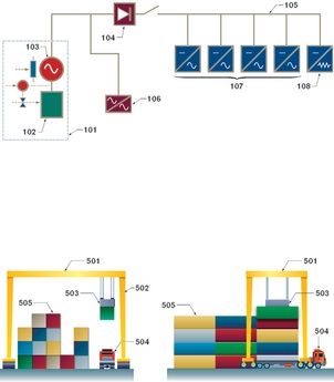
Figure 1 is a prior art schematic of an?RTG crane power system. Figure 2a and 2b is a schematic view showing a hybrid RTG crane loading a container on a truck.
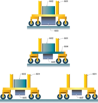
Figure 3A (far left), B (left) and C show a side schematic view showing various possible locations for a prime power source and energy storage system for a hybrid RTG.
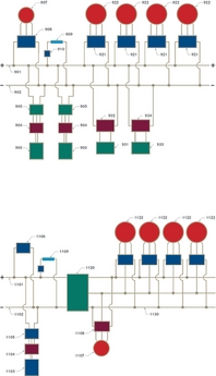
Figure 4 is a block schematic of the elements of a multi-engine and multiple energy storage system hybrid crane power system. Figure 5 is a block schematic of the elements of a hybrid crane power system with an AC bus.
About the application
US patent number 7,546,929 was awarded to Jerry J Wierzba and John E Braun (the assignee was Marine Travelift, Inc.), of Sturgeon Bay, Wisconsin, on June 16, 2009.
Disclaimer
As edited versions of the originals, this article and accompanying drawings may omit legally or technically important detail.


