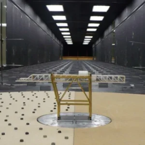
Generally, these carriages have two parts. First, there is a central beam placed at a right angle to the girders. Second, there are clamps at the extreme of the central bridge beam that engage the gantry.
One or more engines move the carriage along the side beams. In one design, the carriage has a single central engine equipped with two side driveshafts and pinions. However, this solution is technically difficult to implement and can prove to be expensive.
In another design, two distinct engines drive each of the two clamps of the carriage. The two engines must be synchronized, which generates considerable extra costs and requires more maintenance than the single-engine design would. The risk of jamming remains if the clamps are not moved strictly simultaneously and with the same speed. The carriage can jam if the shift between the positions of the two clamps is only a few millimetres – a level of precision which the synchronisation methods do not offer.
In addition, it is difficult to manufacture beams that are straight over a great length – 20 metres, for example. Deformation in the beams due to this kind of variation in manufacturing can also lead to the carriage becoming jammed. The beams can also deform over time.
The solution
The invention aims to solve the problems arising from previous designs, by proposing an economic carriage and a gantry guaranteeing the precise displacement of the carriage without the risk of jamming between the side beams. It achieves this despite the beams being out of parallel or in conditions where the two clamps’ displacements are not synchronised with each other.
The invention has three main parts. First, clamps (5, 6) are placed at the lateral ends of the carriage and connect the carriage to a lateral girder to enable the movement of the carriage along the longitudinal axis (x) of the lateral girders. The second part is a central girder which is placed between the clamps. The third part is the connections between the carriage and the clamps.
There are two joints at each end of the central girder. Each joint is made up of two adapter plates. The first joint (54, 29, 56c, 15c) links the right-hand side of the girder with the clamp on the right-hand girder. The second joint (58, 56a, 15a, 56b, 15b) links the left-hand side of the girder with the left-hand clamp. The adapter plates are built so that one connector plate can move in relation to the other with six degrees of freedom.
Because the central beam is not solidly fixed to the clamps, the clamps can move with respect to each other. This movement – which is effectively a deformation of the carriage – prevents jams from occurring.
How they engage
The adapters 35 and 37 are rigidly fixed to the central beam 7 of carriage 4. They are intended to link to the adapters 11 and 12 rigidly fixed to clamps 5 and 6, thus forming a joint at each end of the central beam. This joint connection allowing the displacement of the central beam 7 compared to the clamps, and thus also the displacement of a clamp compared to the other (see figures 4-6). Both joints have an upper and a lower connection point.
First we examine the linkage between the right-hand clamp 5 with the end 34 of the central beam 7. The upper part of the clamp 5 is linked to the end 34 of the central beam 7 by a kneecap connection formed between adapter plates 11 and 35 by the co-operation between the segment of a sphere 54 and bevelled ring 29. The sphere is mounted on top of the bevelled ring and the centres of the two are the same.
In addition, the lower part of the first clamp 5 is associated with the end 34 of the central beam 7 by means of transverse sliding motion. To this end, a stem 56c is vertically inserted upwards in the space 19 inside the hollow U-shaped connector 15c, and is fixed rigidly inside a hollow roll 43c. A means of axial blocking 57, such as a disc, is envisaged on the stem, under the U-shaped connector 15c. This disc allows vertical displacement to the top of the adapter 35 compared to the adapter 11 but it limits the amplitude of this displacement. A vertical play is also envisaged between the lower face of the hollow roll 43c and the higher face of the U-shaped connector 15c.
Thanks to this longitudinal play and transverse play, the the adapter 35 can rotate around the adapter 11, but this rotation is limited in the x and y axes. Of course, the rotational movement around axis Z is possible by swivelling around axis 30,52.
Now we describe the association of the second clamp 6 with the other end 36 of the central beam 7. The clamp adapter plate 12 connects to the beam-end adapter plate 37. Adapter plate 12 also has upper and lower parts whose U-shaped connectors 15a, 15b link into the stems 56a and 56b on adapter 37. The first stem 56a is inserted in the space 19 in the hole of U-shape connector 15a and is fixed rigidly inside the hollow roll 43b. A disc 58 is fitted below the the lower face of the hollow roll 43a and above the upper face of the U-shaped connector 15a, thus forming a pedestal bridge bearing.
A second stem 56b is inserted in the U-shaped connector 15b, and fixed rigidly inside the hollow roll 43b. A means of axial blocking 59 is envisaged on the stem 56b in the same way as 57 on the other clamp-beam connection. The two stems 56a and 56b are virtually identical and have virtually identical centres. This longitudinal play and transverse play allows a movement of the kneecap joint around axes x and y, but this movement is limited.


