Doubtlessly the occurrence of load fall is an intrinsic risk to hoisting equipment and practically impossible to be avoided in two cases, at least:
– rope disruption;
– load block breaking.
In order to minimise those risks, preventive actions strongly supported by inspection routines, must be taken. For the other inherent risks, crane designers provide some protective devices and/or systems, developed through time with basis in their knowledge and experience. Some of those protections are:
– overload detection (OLD);
– over-torque detection (OTD);
– over-speed detection (OSD);
– mechanical discontinuity detection (MDD);
– motion incoherence detection (MID).
Even though some manufacturers offer over-torque and over-speed prevention, hoisting protections are commonly limited to overload detection. Since correctly specified, mounted, adjusted and periodically checked, overload detection certainly appears as an efficient protection. The last three above mentioned protections (OSD, MDD and MID) can be many times unknown for crane designers, but surely they have a vital importance against load falls. This article discourses over those three hoisting protections related with speed and motion, its parameters and how to easily implement them.
Over-speed detection (OSD)
Rarely applied, over-speed detection is an extremely important protection for a safe hoisting operation. It can interrupt a load fall by powering off the drive and applying the brake at the beginning of the failure. When using a frequency inverter with a pulse generator for speed feedback (FVC with PG), a simple parameter adjustment can inhibit the over-speed occurrence. This method, however, seems like a non-effective form of protection since it measures motor speed and not drum speed. It is clear that, for instance, in the case of a mechanical coupling failure, motor speed continues following the operator reference while motion direction goes to down and drum speed normally increases. In such situations, regardless of the operator detecting the problem, he will try to hoist up, as a natural reaction to avoid load fall, but without success.
Remember that to inverters, speed feedback is not a protection feature but a control feature. The correct way to obtain speed value for protection purposes is to measure it closer to the drum, at low speed side. We can do it by installing an incremental encoder at the drum axle and comparing the actual value to a secure upper limit.
For the correct operation of an OSD, the following hints must be considered:
– safe values for the detection are between 105% and 115% of the maximum rated speed;
– if over-speed occurs, drive must be immediately powered-off and restart must be blocked. Also, the operator should be advised;
– OSD protection only works efficiently when associated with a safety brake placed at the low speed side of the hoisting mechanism.
OSD protection can only be a passive system since it is practically impossible for the operator to quickly react to prevent the occurrence of that type of failure. Over-speed generally indicates a load fall and therefore an automatic action must be taken immediately.
Mechanical discontinuity detection (MDD)
As well as over-speed detection, the mechanical discontinuity detection is highly recommendable for any geared type of hoist mechanism, but rarely applied. It is based on the fact that the drive reduction factor must be a constant, that is to say, to an input value of speed (motor) will always correspond to an output value at low speed side (drum), determined by the reduction relation. Thus, if we have a motor speed S1 of 1200RPM and a reduction relation of 1:30, drum speed S2 will be obligatorily equal to 40RPM just because 1200×1/30=40. An MDD system measures the two speeds, divides S1 by S2 and compares the result with the reduction relation. When the difference exceeds an adjusted limit the protection acts. As motor and drum speeds must be measured, MDD needs an incremental encoder at motor side, more than that used for OSD at drum side.
For the correct operation of over-speed protection, the following hints must be considered:
– safe values for the detention are between 102% and 105% of difference in the rated reduction relation;
– if mechanical discontinuity occurs, drive must be immediately powered-off and restart must be blocked. Also, again, the operator should be advised;
– this protection only works efficiently when associated with a safety brake placed at the low speed side of the hoisting mechanism.
Due to the same reasons explained for over-speed detection, the mechanical discontinuity detection can only be a passive system and must start an automatic action. This protection detects breakings in the driving train like coupling disruption, brake failure and gearbox internal disconnection.
Motion incoherence detection (MID)
This protection works to prevent an unexpected movement in the hoisting mechanism. By comparing the actual direction of the movement with the order generated by the operator, it detects a wrong response to the command and acts to power-off the drive and to advise the operator. By specifying the MDD encoder for drum speed measurement with A and B channels, the direction of movement can be easily achieved by using simple logic detection circuit.
Low speed feedback (LSF)
As already explained, OSD, MDD and MID are important techniques to prevent and/or avoid load fall. For those purposes some dedicated or customised systems that perform all those protections can be found by crane designers. Anyway, instead of those existing systems, OSD, MDD and MID can be easily implemented by connecting the encoders to a PLC. Software can be easily developed by skilled people. But if the economical aspects can affect the decision to increase the hoisting safety, the choice can lead to a new, cost effective and creative solution: low speed feedback (LSF).
This interesting philosophy starts ‘deceiving the inverter’ by simply replacing, from the motor to the drum, the measuring point for speed feedback. Through a decent parameterisation the inverter will effectively perform OSD, MDD and MID protections. The LSF uses no PLC, no software and no other additional components than the following:
– one high resolution (HR) incremental encoder; and
– one encoder input module (EIM), normally supplied as an accessory for the inverter.
Some models of inverter are already supplied with the EIM; consult your inverter manual.
Encoder resolution must be in such a range that permits, at least, to maintain the control accuracy. The new generation of interpolated optical encoders are able for this task because they can reach high numbers of counts per revolution (CPR).
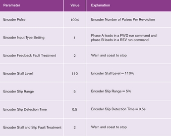
Models like the Allied Motion CP-850-HHC can reach 1,250,000 CPR in a maximum frequency of 2MHz, in a quadrature signal (A and B channels). The CPR to be declared to the inverter will result in the encoder CPR divided by the denominator of the reduction relation. For instance, if the original motor encoder is an 1024 CPR and the reduction relation is 1:234, the nearest standardised HR encoder will be that of 256,000 CPR. That is because 256,000 divided by 234 results in 1094, so the control accuracy is a little bit improved.
Back to the inverter, it follows an example of parameterisation for a generic equipment.
Conclusion
LSF philosophy can be freely modified and adapted to the conditions both of new and existing equipment. If the idea is to use a sensorless control mode (seems to be the current trend), simply by changing to LSF the drive is improved in accuracy (SLVC to FVC with PG) and effective protection resources. Think about it before planning your next crane.