Plate clamps
5 August 2010As he continues his series of buyer’s guide articles about lifting accessories, Derrick Bailes, technical consultant, Lifting Equipment Engineers Association, offers some expert advice on the use of plate clamps.
Not every load can be connected to in this way, but there are alternatives. These rely upon friction, such as clamps and grabs, or adhesion, such as vacuum lifters and magnets. I start this group by looking at plate clamps.
Plate clamps have a long history but it is only relatively recently that there has been a standard for them. As a result, the performance of many early designs varied widely from one manufacturer to another. Some could only be used to lift vertical plates. Others could lift a plate from horizontal to vertical but could not then lower it to the other side to complete a turning over operation. Some would release the plate if set down on edge or if the weight of the crane hook pushed down onto the clamp. The result was a degree of confusion about how they should be used—and rather too many dangerous incidents. Plate clamps can have a long life so this should be borne in mind when reviewing the suitability of existing equipment.
Plate clamps are included in EN 13155: 2003 – Non-fixed load lifting attachments. This is a harmonised European Standard, which means that equipment complying with it is deemed to comply with the European legislation.
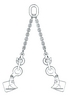
Plate clamps generally fall into one of two distinct categories, horizontal and vertical. As the name implies, horizontal plate clamps are designed to lift plates only in the horizontal plane. They are always used in pairs connected by a suitable sling. Figure 1 illustrates a typical arrangement.

Figure 1 – Typical arrangement of horizontal plate clamps
The plate is clamped between the clamp frame and the moveable jaw. The clamping force comes from the weight of the load transmitted through the sling legs. The amount of clamping force therefore depends not only on the weight of the load but also on the angle of the sling legs to the vertical. This angle also controls the line of pull onto the clamp mechanism. It is therefore vital that the sling chosen gives the correct geometry for the width of plate being lifted. The manufacturer’s instructions for their clamps should provide this information.
The force in the sling legs has a horizontal component and, because the plate is only supported at its edges, this tends to bend the plate inwards across its width. Clearly if the plate is very flexible it could simply sag to the point where it may be damaged or even released. However, a short plate can usually be lifted with a single pair of horizontal plate clamps located centrally. If the plate is allowed to flex and the ends to sag, this curvature will make it much more rigid across its width. There is a limit as to how long a plate can be lifted with a single pair of clamps. Clearly at some point the self-weight of the plate will cause permanent deformation. Therefore for a long plate, two or more pairs of clamps used in conjunction with a lifting beam are required.
Although I have referred above to a plate in the singular, this type of clamp can often be used to lift more than one plate at a time. However caution is needed with thin sheets, particularly if oiled.
There is a variant of the horizontal plate clamp, which does not have a moveable jaw to clamp the plate. This is effectively a plate hook, which engages with the edge of the plate. Like the clamp, they must be used in pairs with a suitable sling. They rely upon the horizontal component of the force in the sling legs to grip the plate and because of this the force is usually much higher than for the clamps. The higher force comes from either a greater angle between the sling legs and the vertical or by reeving an endless loop through the hooks. Because of the absence of clamping and the relatively high gripping force, this variant is only suitable for lifting single, thicker, more rigid plates.
The second category is the vertical plate clamp. This is a rather inaccurate name as most modern clamps falling into this category are capable of handling plates in many orientations as well as vertically. In fact some manufacturers offer products described as universal plate clamps, which have few limitations on the orientation of the plate.
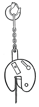
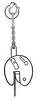
Figure 2 – Typical vertical plate clamp
Figure 2 illustrates a typical modern vertical plate clamp. It has a rigid frame holding a fixed jaw and a moveable jaw. Once placed over the edge of the plate, the moveable jaw is brought into contact with the plate by operating a spring-loaded lever. The moveable jaw is cam shaped and linked to the lifting point. Thus the spring provides the initial grip, the moveable jaw adjusts to the thickness of the plate and, as the weight of the plate is taken, the linkage and cam action ensure the necessary clamping force.
EN 13155 requires that this clamping force generates a frictional resistance of at least twice the weight of the load. It also requires that the clamp can withstand a static load of twice the working load limit without permanent deformation and three times the working load limit without releasing the load even if permanent deformation occurs.
Another key requirement of the standard is that it should not be possible to unintentionally release the load. This applies particularly during any of the permitted movements such as turning or orienteering the plate and when it is being set down. The weight of the crane hook or other connections must not release the load nor must inadvertent contact of the clamp or locking mechanism with an obstacle. Some designs incorporate a short length of chain to connect the clamp to the crane hook to prevent it bearing down on the clamp.
The clamp design must take account of the likely tolerances on plate thickness. The smallest sizes will start at zero thickness but larger clamps will have a minimum as well as a maximum plate thickness. The design must allow for the tolerances on a plate of nominal thickness equal to the clamp’s minimum thickness.
Since the standard was published it has been found that some clamps do not perform well with thin light plates. This is being addressed by an amendment. Meanwhile the guidance issued by the LEEA is that, in the absence of specific guidance by the manufacturer, the load should not be less than 20% of the WLL and the plate thickness should be not less than 20% of the maximum. To be fair, clamps from the reputable manufacturers perform much better than this and their instructions for use reflect that.
Vertical plate clamps to the standard can lift and transport a plate vertically. They can also lay a plate down from the vertical to the horizontal and turn a plate over from horizontal through vertical to lay down on the other side. During these operations, the bottom edge of the plate will remain in contact with the ground, hence the importance of the clamp not unintentionally releasing the load when there is little weight on it.
Vertical plate clamps can only lift one plate at a time and they should engage fully with the plate, square to the edge. The line of pull must always be in line with the clamp. Therefore a single clamp should be positioned centrally on the plate so that it will hang vertically. For larger plates, two or more clamps can be used in conjunction with a lifting beam but, due to the very rigid nature of a plate on edge, care is required to ensure an even share of the weight. Two or more clamps can also be used to lift a plate horizontally or at an angle.
The universal clamp designs show their advantage when the line of pull required is not square to the plate edge. The linkage in this type of clamp permits loading at an angle. This means that irregular shaped plates can be lifted either by a single clamp or a pair of clamps suspended from a two-leg sling.
The majority of vertical plate clamps are intended for handling rolled steel plate for fabrication applications. The fixed and moveable jaws of the clamp have teeth, which bite into the surface of the plate to ensure a good grip, thereby leaving marks. However clamps are also manufactured to handle other types of plate, including those with a hard surface finish or one, which must not be marked or damaged in any way. The jaws of these types are usually lined with a smooth friction grip material.
In this article I have covered the most popular types of plate clamps. However there are others, including some for specific applications. When properly designed, maintained and used in accordance with the manufacturer’s instructions, they provide a solution to the otherwise difficult problem of connecting to this type of load. However I do wish to emphasise ‘properly designed, maintained and used’. Beware of low cost copies of reputable brands, regularly inspect and maintain clamps as necessary, and ensure the end user is fully conversant with how they are designed to be used.
About the author
Derrick Bailes is technical consultant (formerly chief executive) for the Lifting Equipment Engineers Association, 3 Osprey Court, Kingfisher Way, Hinchingbrooke Business Park, Huntingdon, PE29 6FN, tel: +44 (0)1480 432 801, fax: +44 (0)1480 436 314, email: info@leea.co.uk