Going home
12 November 2009Steven K. Waisanen, of Big Bend, Wisconsin has received a US patent for a crane return system used for returning a crane component to a home position when there is a loss of power.
When power is lost to the crane, hydraulic fluid is supplied to the hydraulic cylinder to extend the hydraulic cylinder and thereby move the auxiliary drive wheels from the first position to the second position.
Technical illustrations
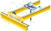
Figure 1 illustrates an overhead crane (10) that positions a hoist (14) in a crane bay for lifting and unloading a load. The overhead crane (10) includes a bridge (18) that translates along a first main support beam (22) and a second main support beam (not shown). The main support beams (22) generally extend between two walls (not shown) of a facility and are spaced apart and generally parallel to each other. As will be readily known to those of skill in the art, the main support beams (22) may alternatively be curved to match the inside wall contours of a round building, or include a single, curved support beam.
In the illustrated embodiment, top surfaces of the first and second main support beams (22) define rails (26) that the bridge (18) travels along. The bridge (18) includes a first girder (30), a second girder (34), and a pair of end trucks (38) that extend between the first and second girders (30, 34, only one end truck [38] is shown in Figure 1).
The end trucks (38) or U-shaped channel members, are aligned generally parallel to the main support beams (22). Each end truck (38) defines a passage for receiving one of the main support beam rails (26). Main wheels (42) are disposed in each passage to facilitate travel of the bridge (18) along the rails (26). As will be readily known to those of skill in the art, any number of driven wheels may be disposed in the end trucks (38).
Furthermore, idle wheels may be disposed in the end trucks to facilitate travel of the bridge (18) along the main support beams (22).
The end truck shown in Figure 1 supports an auxiliary end truck (46) that includes a plurality of auxiliary drive wheels (50). The auxiliary drive wheels are movable between a first position, in which the wheels (50) are recessed from the rails (26), and a second position, in which the wheels are in contact with the rails.
Girders
The first and second girders (30, 34) are spaced apart from each other and generally parallel. The girders are aligned transversely to the main support beams (22). A trolley (54), or second bridge, travels along girder rails (58, 62) that are positioned on top surfaces of the first and second girders. The trolley (54) includes a pair of end trucks (66, 70) that are aligned generally parallel to the first and second girders. Each end truck defines a passage for receiving one of the girder rails (58, 62).
Wheels (not shown) are disposed in each passage to facilitate travel of the trolley (54) along the rails.
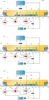
Figures 2-6 are schematic diagrams illustrating a crane return system (80) for returning the crane (10) to a home position upon loss of power, power failure or mechanical failure of a crane component, and also illustrate sequence of operations for the crane return system (80).
The crane return system (80) includes the main end truck (38) including main wheels (42), the auxiliary end truck (46) including auxiliary drive wheels (50), a hydraulic fluid pressure vessel (84), a pair of hydraulic cylinders (88), a hydraulic reservoir (92), a pump (96), a hydraulic drive motor (100), and multiple limit switches and valves as discussed below.
In the illustrated embodiment, the main end truck forms part of the bridge (18) and supports the main wheels (42), which travel along one of the rails (26) of the main support beams (22) during normal operation of the crane. The auxiliary end truck (46) is supported by the main end truck (38) and includes the auxiliary drive wheels (50). The auxiliary drive wheels are movable between a first position (shown in Figures 2-6), in which the wheels are recessed from the rail (26) of the main support beam (22), and a second position (shown in Figures 3-5), in which the wheels are in contact with the rail.
Hydraulic fluid
The hydraulic fluid pressure vessel (84) stores hydraulic fluid, wherein a substantially fixed mass of hydraulic fluid is contained within the crane return system (80). The hydraulic cylinders (88) are coupled to the auxiliary end truck (46) and fluidly communicate with the fluid pressure vessel (84). When the cylinders (88) extend, the auxiliary end truck (46) moves toward the rail (26) to thereby move the auxiliary drive wheels (50) to the second position and bring the wheels (50) in contact with the rail (26).
When the cylinders (88) retract, the auxiliary end truck (46) retracts away from the rail (26) to thereby move the auxiliary drive wheels (50) to the first position and recess the wheels (50) from the rail (26). A normally-closed power loss valve (104) regulates flow of hydraulic fluid from the fluid pressure vessel (84) to the cylinders (88).
A wheel down valve (108) regulates flow of hydraulic fluid from the fluid pressure vessel (84) to the drive motor (100) and flow of hydraulic fluid from the fluid pressure vessel (54) to the hydraulic cylinders (88). The wheel down valve is shown as a three-way valve in Figures 2-6. Further, a normally-open home position valve (112) regulates flow of hydraulic fluid to and from the drive motor (100).
The hydraulic fluid reservoir (92) fluidly communicates with the hydraulic cylinders (88), the hydraulic drive motor (100), and the hydraulic fluid pressure vessel (84). The fluid reservoir (92) receives hydraulic fluid from the cylinders (88) and the drive motor and stores the hydraulic fluid until the pump (96) pumps the hydraulic fluid to the fluid pressure vessel. A normally-closed system reset valve (116) directs flow of hydraulic fluid from the fluid reservoir (92) to either the fluid pressure vessel or the cylinders.
Crane return system
Figure 2 illustrates the crane return system (80) when power is supplied to the crane (10), for example, during normal operation. In Figure 2, the main wheels (42) are in contact with the rail (26) such that the main wheels (42) travel along the rail (26) to move the bridge (18). The auxiliary drive wheels (50) are in the first position, recessed from the rail (26), and the hydraulic cylinders (88) are retracted.
While power is supplied to the crane, hydraulic fluid in the hydraulic fluid reservoir (92) is pumped to the hydraulic fluid pressure vessel, shown by a hydraulic fluid flow path (120, bold line in Figure 2).
The fluid pressure vessel (84) sits as potential energy. Once the fluid pressure vessel (84) is full, a pressure relief valve reroutes hydraulic fluid back to the fluid reservoir (92).
In Figure 2, the power loss valve (104) is closed to prevent hydraulic fluid from exiting the hydraulic fluid pressure vessel (84) to the hydraulic cylinders (88). The system reset valve (116) is closed to prevent hydraulic fluid being pumped from the hydraulic fluid reservoir (92) from entering the cylinders.
The wheel down valve (108) is positioned to prevent hydraulic fluid from exiting the fluid pressure vessel and entering the hydraulic drive motor to energize the drive motor. When power is supplied to the crane, the home position valve (112) is open, however, no hydraulic fluid passes through the valve because the wheel down valve (108) is closed.
Figure 3 illustrates the crane return system (80) immediately upon loss of power to the crane. Upon loss of power to the crane, the normally-closed power loss valve (104) opens to allow hydraulic fluid to flow from the hydraulic fluid pressure vessel (84) to the hydraulic cylinders (88). Hydraulic fluid delivered to the cylinders (88) causes the cylinders to extend, thereby extending the auxiliary end truck (46) towards the rail (26) of the main support beam (22) until the auxiliary drive wheels (50) come in contact with the rail.
Contact
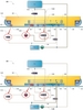
Figure 4 illustrates the crane return system after the auxiliary drive wheels contact the rail of the main support beam. A wheel down limit switch (128) is coupled to the wheel down valve (108) and positioned adjacent the auxiliary drive wheels (50). In the illustrated embodiment, the wheel down limit switch (128) is located on the auxiliary end truck (46). When the auxiliary drive wheels (50) contact the rail (26), the wheel down limit switch (128) contacts the rail (26) and actuates the wheel down valve to allow hydraulic fluid to flow from the hydraulic fluid pressure vessel to the hydraulic drive motor.
Thus, the wheel down valve is positioned to prevent flow from the fluid pressure vessel (84) to the hydraulic cylinders and the cylinders stop extending. (A hydraulic fluid flow path (132) is shown by the solid, bold line in Figure 4).
Force from the auxiliary drive wheels (50) contacting the rail (26) lifts the main wheels (42) from contact with the rail (26) and the main end truck (38) retracts from the rail (26). Hydraulic fluid is delivered to the hydraulic drive motor (100) from the hydraulic fluid pressure vessel (84), via the wheel down valve (108).
During this phase of the crane return, the home position valve (112) and the system reset valve (116) remain in the respective initial position. The home position valve remains open to permit hydraulic fluid to flow from the hydraulic drive motor to the hydraulic fluid reservoir (92), whereby the pump (96) pumps hydraulic fluid back to the hydraulic fluid pressure vessel.
Figure 5 illustrates the crane return system after the crane reaches the home position. A home position limit switch (136) is coupled to the home position valve (112) and positioned proximate an end (140) of the bridge (18). The home position limit switch (136) may be activated in a number of ways, including, but not limited to, contact with the home position or with an object at the home position.
The home position limit switch (136) actuates the normally-open home position valve to a closed position, which stops flow of hydraulic fluid from the hydraulic fluid pressure vessel (84) to the hydraulic drive motor (100).
Again, a hydraulic fluid flow path (142) is shown by the solid, bold line in Figure 5.
Restoration of power
Figure 6 illustrates the crane return system subsequent to restoration of power to the crane. When power is restored to the crane, hydraulic fluid is used to retract the hydraulic cylinders and move the auxiliary end truck and auxiliary drive wheels back to the first position, for example, recessed from the rail of the main support beam.
During this phase of the crane return, the normally-closed system reset valve (116) is actuated open, for example, to a second position, such that hydraulic fluid flows between the hydraulic fluid reservoir (92) and the hydraulic cylinders (88). The pump pumps hydraulic fluid from the fluid reservoir (92) to the cylinders (88), which thereby retract to pull the auxiliary end truck (46) and the auxiliary drive wheels (50) away from the bridge rail (26). After the hydraulic fluid cycles through the cylinders (88), the hydraulic fluid returns to the fluid reservoir (92). A hydraulic fluid flow path (148) is shown by the solid, bold line in Figure 6.
Once the auxiliary drive wheels (50) are lifted from contact with the rail (26), the force lifting the main end truck and the main wheels from the rail is released. This phase of the crane return is illustrated in Figure 2.

Figure 1 – a perspective view of a crane.

Figures 2-4 – schematic diagrams that illustrate a sequence of operations for a crane return system embodying the invention.

Figures 5-6 – schematic diagrams that illustrate a sequence of operations for a crane return system embodying the invention.
About the application
US patent number 7,597,0505 was assigned to Steven K. Waisanen on October 6, 2009.
Disclaimer
As edited versions of the originals, this article and accompanying drawings may omit legally or technically important detail.