Crane control for human push
21 November 2006Gorbel, Inc. of Fishers, New York, has been assigned a US patent for the development of a crane control apparatus and method invented by Laundry et al, all of New York state. The system is intended for use with overhead cranes with a line and load suspended from a moveable hoist, and to make it easier and safer for an operator to move the load laterally with manual forceOur patents are edited for publication by Maurice Jones
This new patent (US Pat. No. 7,028,856) refers to earlier patents and developments involving power-driven cranes to move a hoisted load laterally in response to manual effort. In these the crane drive responds to the manual force to move in the direction and distance required. However a problem with this action is a pendulum effect of the hoisted load swinging initiated by a momentary delay in the movement of the load when the hoist starts travelling.
The reverse pendulum swing can then cause the hoist to move in the wrong direction, and so on, resulting in a dithering motion. The new development addresses this problem but, unlike previous developments, not by suppressing the oscillations of the load.
The inventors consider this approach to be secondary and feel that it is more important to control the impedance felt by the operator pushing on the hoisted load. Their control strategy places the human operator in the outer control loop via an impedance block that is used in making trajectory generalisations.
How it works
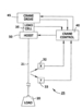
In Fig 1 the hoist (50) supports, via a line (21), a load (20) which is pushed by the operator to urge it in the desired direction. Sensors (25), probably situated below the hoist, are arranged to sense the direction and angle by which the line is deflected. The crane system responds to the input force from the operator on the load, using the crane drive (45) to drive the sensors and hoist to the desired location.
The crane drive may be a hoist trolley, or a movable crane bridge, controlled by a typical state-of-the-art crane control. Two of the sensors are suitable (mechanical, electromechanical, or optical) to monitor the direction of swing movements on the 'x' (32) and 'y' (33) axes. These are connected to the crane control (40) to supply amplitude and directional information. If required, the crane control can also accept input on the force or mass of the load sensed by a load cell or strain gauge as examples. The hoist position can also be transmitted to the crane control by standard methods.
Software in the crane control receives data from the sensors (above) and actuates the crane drive to move the crane trolley and/or bridge in the direction indicated by the operator's push. The control software is designed to deal with the pendulum effects that this movement will initiate, as well as responding appropriately to the force input from the operator.
Mathematical basis
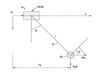
A major part of the invention is concerned with the mathematical basis for treating the data sensed as above. The inventors say that the pendulum effects can best be treated by considering each axis of motion (x and y). As modelled in Fig 2, the system comprises a simple pendulum with a point of support (at the crane drive and hoist) that changes its position along the specified axis. That patent discloses a formula in which the following elements are related by means of matrices:
m1 = mass of the hoist and crane drive
m2 = mass of the hoisted load
l = length of line or wire rope
? = angle of the line
b1 - static friction along the 'x' axis
b2 = viscous damping along the 'x' axis
b? = viscous joint damping
Fx = force applied to mass m1 in response to signals received from the crane control
Fhx = force applied to the load by the operator
Substitution of the matrices in the formula leads to two equations of motion for the generalised co-ordinates position x and angle ?:
(picture clipping to go here)
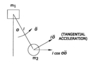
If the linear equation of motion (for 'x') is seen as a unified system it can be described using Newton's Second Law. However m2 is also rotating with an angular acceleration, inducing another active force onto the entire motion (see Fig 4). The inventors also cite a 'pseudo-force' called the Coriolis Force, which comes into effect as ? increases, and the velocity along the x-axis gets smaller in a similar manner to that of the acceleration.
This phenomenon acts as if an opposing frictional force is reducing the velocity, which is represented in the patent by a formula. Typically the opposing frictional forces are modelled as a viscous friction proportional to the velocity, and a coulomb friction that remains constant and against the direction of movement.
The Angular Equation of Motion refers to the rotation of m2 about m1, and the inventors employ Newton's Second Law in the torque equation to develop an expression for the resisting torque from the gravity effect on m2. The viscous joint damping friction compensates the input torque. As the entire system is moving in Fig 4, if m1 suddenly slows down whilst m2 is still moving linearly at the original acceleration, then it will rise up in a calculable effect, again following Newton's Second Law.
Thus the inventors disclose a linearised equation for X involving the measured states of the wire rope angle ? and the x position of m1 from which a matrix is developed as a nominal control system, which is controllable and observable.
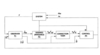
Control System
Fig 3 shows a schematic control system with each axis of movement controlled independently. Therefore it would be usual to have two crane controls with the same structure but with different parameters and settings. Assuming that the force applied by the operator is not measurable, the system works with only measurements of the hoist and drive mass m1, and the wire rope angle ?. The control system results in the application of an appropriate force Fx to m1 via the crane drive. A linear observer block (41) is used to obtain an estimate of Fhx resulting in this equation in a system that is also controllable and observable.
(picture clipping one to go here)
The pushing force Fx on the load mass m1 is given by:
(picture clipping two to go here)
Where bls is the static friction on the x-axis and ?>0. The above equations describe the static friction compensation for the observer block taking into account the cases:
When m1 is at rest and the observer block is as a simple pendulum
When m1 is moving and the static friction is subtracted from the control input Fx.
The observer block also generates filtered values for the 'cart' position, velocity, wire rope angle and angular velocity.
The estimated operator force is used to generate the desired position of the load by passing it through the impedance block (42) as:
(picture clipping three to go here)
Where Md is the desired mass, Ba is the desired damping and Xcd is the desired position of the load. A particular performance for the load motion can be specified through the impedance block, and it also enables the load 'feel' for the operator to be changed from very light (almost no damping) to heavy and viscous (extreme damping).
The correction block (44) is used to obtain x co-ordinates in the absence of control on the load position.
The control block (43) is a simple pole-placement controller, but others can be used, to track the reference trajectory. Anti-swing can be achieved with desired load impedance if the conditions of a disclosed formula are met with specific locations of the system poles.
Testing
The inventors have carried out experiments with the system that have revealed some uncertainties with parameters, which they have had to deal with. These included variation in friction on the crane drive runways, changes in the length of the wire rope, and inaccuracies of the measurement of ?.
These differences between the model and the real system result in a non-zero observer force that can drive the crane. The inventors therefore use dead zones for some signals, the thresholds of which are a function of the angular velocity.
Summary
The inventors say they are presenting a viable means of controlling an overhead crane using an estimation of the force applied to the load. Using a linearised system, a controller-observer was designated using the placement of the closed-loop poles for both the system and the observer.
With the use of the dead zones on non-linear elements mentioned previously the inventors could work with a simple model of the system, and yet obtain a relatively clean estimate of the applied force Fh.
Tests with different loads and wire rope lengths, as well as constant loads and wire rope lengths, were performed and confirmed that the controller system is robust to variations of both the load m2 and wire rope length l.
CLAIMS
A large number of individual claims made in the patent cover features such as the sensing apparatus, the crane control system, the linear observer, use of desirable variable impedance, and the related mathematical formulae developed.
ABOUT THE PATENT
This article is an edited version of US patent 7,028,856. The inventors are Bradford Laundry, Li-te Liu, Gustavo Montemayor, Dan Popa, Michael Taylor and John Wen, all of various towns in New York state. The assignee is Gorbel, Inc. headquartered in Fishers, New York. The patent application was a continuation in part of US Pat. 6,696,447 entitled 'Crane Control System'. It also incorporates Provisional Patent Application No. 60/257,850 of February 2001.
DISCLAIMER
This article is an edited version of the patent and may omit legally or technically important text. To see the full patent go to www.hoistmagazine.com/patents
MARKETING
Gorbel manufactures work station cranes, jib cranes, soft touch handles and features. The company also features a range of Intelligent Assist Devices including the G-Force to enable operators to lift and manoeuvre loads naturally 'as if the device were an extension of their own arm', thus improving productivity, reducing the cost of product damage and minimising work-related injuries. For more information visit www.gorbel.com.