Off the hook
14 March 2019Specialised loads need specialised methods of attaching them to the lifting system. Julian Champkin looks at below-the-hook lifting devices.
lifting device is a rope that goes up and down with a hook on the end of it. At least, that is what it used to be. These days, the hooks are often replaced with or augmented by a variety of specialised devices that attach the load to the rope. They can be powered or passive, magnetic, or vacuumpowered, or shaped to carry a specific load that may not have a lift-point for a hook; they can be attached, and released, by hand, or remotely, or automatically; some are hightech, some are basic.
New offerings appear frequently, and old offerings are redesigned and renewed. Here are some of the more recent and interesting developments.
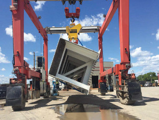
Rotating loads to positions where they can be worked on more easily is usually done by placing them into rotating frames, specially designed for each load.
Wisconsin-based Bushman Equipment have a much simpler and more flexible device, called the Flip-rite. The load, no matter how big, is simply suspended by two slings. Each sling is supported not by a hook but by an electrically-powered small-diameter roller; the two rollers and their motors are mounted in a frame suspended from the hoist. The sling goes over the roller; when the roller starts to turn the sling turns with it; so the load at the bottom of the sling is also rotated. The setup is like a drive belt between two pulleys. The load can be of any shape, regular or irregular, and can delicate and fragile, such as a fibreglass boat cabin, or large and extremely heavy, such as a railway car.
“The load is gently rotated within the envelope of conventional synthetic lifting straps without the shock loading and wear and tear that cranes experience when attempting to flip over heavy loads,” says the company. Capacities can be up to 100t. Elebia’s magnetic automated hook is one of those ideas that appear so obvious once they have been devised, that you wonder why no-one has ever thought of it before. It, too, relies on specialised slings.
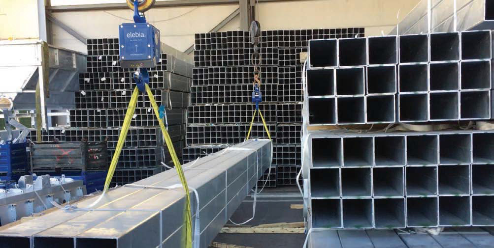
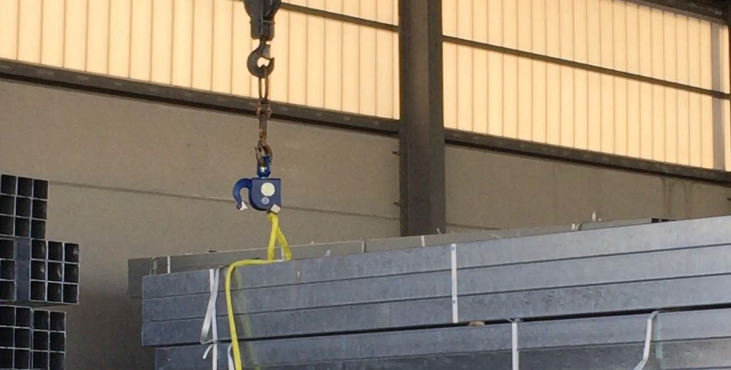
On a recent job, the crane was used to lift 36 box girders in stacks of four by nine, with a sling at each end of the combined load going to Elebia’s magnetic hooks on a dual-lift hoist, but it could be used on anything that is normally lifted via one or more slings.
Elebia’s magnetic evo5 automatic lifting hooks can be used with a selection of slings designed to include ferrous components. On this job, nylon-coated tubular slings, with a wire rope core, were used. Other compatible slings use ferrous components in their handles, or are desogned specifically for use with ‘big bags’ in the building trade.
When the magnetic hooks get close to the sling, the magnet attracts the wire rope, which jumps up to meet it, carrying the sling with it. The hook latch on and close over it automatically, as per Elebia’s tried technology; the end result is a sling which attaches itself to the hook without the need for an operator to climb on top of the load and do the attaching himself. He can control the whole operation from a safe distance by remote control. Release of the load is similarly automatic; so there are clear safety and efficiency gains.
Elebia’s demonstration video shows the system lifting a 4t load using two slings each of 3t capacity, but the slings can be customised in length and working load limit, and the evo range of automatic hooks come also in a range of higher capacities. Elebia’s evo range are magnetic hooks—that is, physical hooks where the attachment process is guided and eased by the magnets.
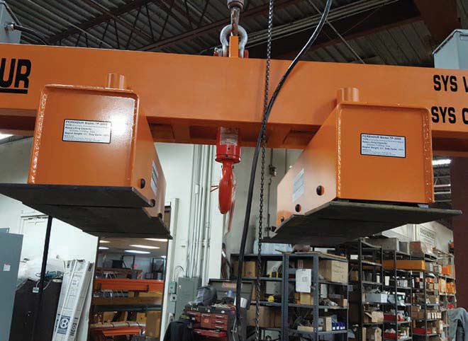
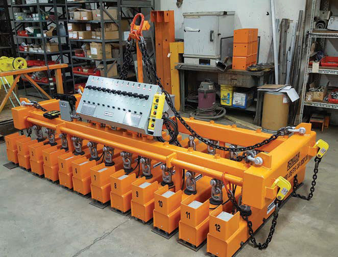
Ferrous metal loads can of course be easily lifted by magnet power alone. Electromagnets have the disadvantage that should power fail, so will their magnetism, and the load will be dropped, perhaps catastrophically. Permanent magnets have the disadvantage that while it may be easy to pick up the load, letting go of it can present a problem. New Jersey-based Permadur Industries have squared an apparent circle by producing an electrically-controlled permanent magnet as a below-the-hook lifting device. A primary application is to lift steel plate to cut or weigh it.
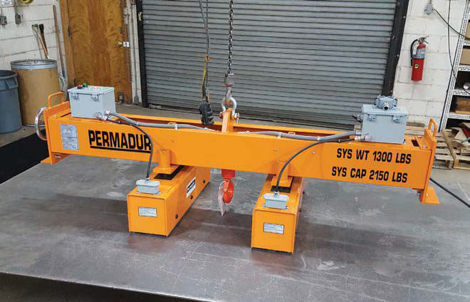
The magnets themselves are made from a ceramic-based material that is permanently magnetised; it gives them immense magnetic strength for their weight. They are mounted singly, in pairs or in pluralities within a frame, to form a single below-the-hook lifting device. The operating principle is both simple and unique. Before lifting, a keeper rests on top of the magnets, joining two or more of them; the magnetic field goes upwards, through the keeper. When magnetic lifting is to be switched on, a short-duration burst of electrical power to an actuator lifts the keeper upwards and off the magnets. Without the keeper to absorb it the magnetic field goes downwards, into the load.
In a simple manufacturing operation, the magnets, with the keeper resting on them, are lowered onto the plate. At that point there is no magnetic field directed downwards; nor is there any sudden application of an intense electrical field as when using electromagnets; this means that the Permadur device will not ‘jump down’ to the load, as can happen with electromagnets.
Once the lift system is resting on the load surface and there is slack in the suspension system, the operator momentarily depresses the ‘on’ control button on his control unit. This causes the electrical system to apply a short impulse of power that lifts the keeper off the top of the magnets poles, so their magnetic field is now directed downward, into the load, and attaches to it firmly.
The lifting rope or wire is attached not to the casing, but to the keeper, so under load the rope tension pulls the keeper upwards, away from the magnets. The arrangement always prevents the magnet from turning itself off under load, even if the controls are accidentally operated.
Once attached, raising the system via its chains or spreader beams will raise the load as needed. The internal electrical components are no longer needed—the magnets hold the load without them— and they sit idle until the next operating command is executed. Thus, failure of the battery power or to any component of the control system will not cause the load to drop. “It is the lifting rope or suspension itself that is holding the keeper in its raised position away from the magnets; it therefore cannot ‘turn off”,” says Joe Pavlosky, Permadur’s general manager. When the load has been moved to its destination, the support rope sets it down and slackens; and the slackening allows sufficient travel within the casing for keeper once again to move downwards onto the magnets, absorbing their magnetic field and releasing the load.
The source of power for the electrical pulses can be a Ni-cad battery. It is mounted directly on the housing itself, or, for a system of many magnets, on the frame. The movement of the internal keeper provides, via a sensor, positive feedback that the magnetic field has either been absorbed by the load or released from the load. The sensor activates a safety indicator light which shows when the actual magnetic attachment has been achieved and it is safe to proceed with a lift and when it has been eliminated.
The lifting device consumes no power once the magnets have attached and when the load is suspended; and, since it uses permanent magnets, neither loss of electric power, nor faulty wiring, nor even operator misuse or mistakes operating the controls can make it drop a suspended load.
For large industrial and large-scale applications there are usually multiple magnet units arranged on a frame that can be customised for any size or plate or for very large loads. “Typical applications are wherever steel plates, steel shapes or steel parts need either to be cut, moved or transported—so, really, part of every manufacturing situation,” says Pavlosky. In a “who-lifts-the-lifters” scenario, crane manufacturers including Manitowoc Crane and Gorbel Crane use Permadur below-thehook systems for both lifting their steel plates and removing the cut parts in their factory. Curiously, thinner plate materials need proportionately more powerful magnets to safely lift them. This, says Pavlosky, is because thinner plates cannot absorb as much magnetic flux. Additionally, systems must take into consideration deflection because thinner materials flex when they are not properly supported when suspended. The deflection introduces spaces below the magnet, or “air gaps” as they are called in the industry, which reduce the contact area between the flat magnet and the now-curving plate, so it reduces their effectiveness.
In an era of digitisation and Industry 4.0, precision in parts placement and the positioning of heavy loads is becoming ever more important. Sometimes the positioning must be very precise indeed. Positioning by accurately controlled hook in assembly work has increased dramatically over recent years. However, achieving the last millimetre or so of fractional accuracy is inherently difficult, if not impossible, for a hook suspended from a crane or hoist by several metres of wire, rope or chain which itself is being let out or taken in from a large-diameter drum.
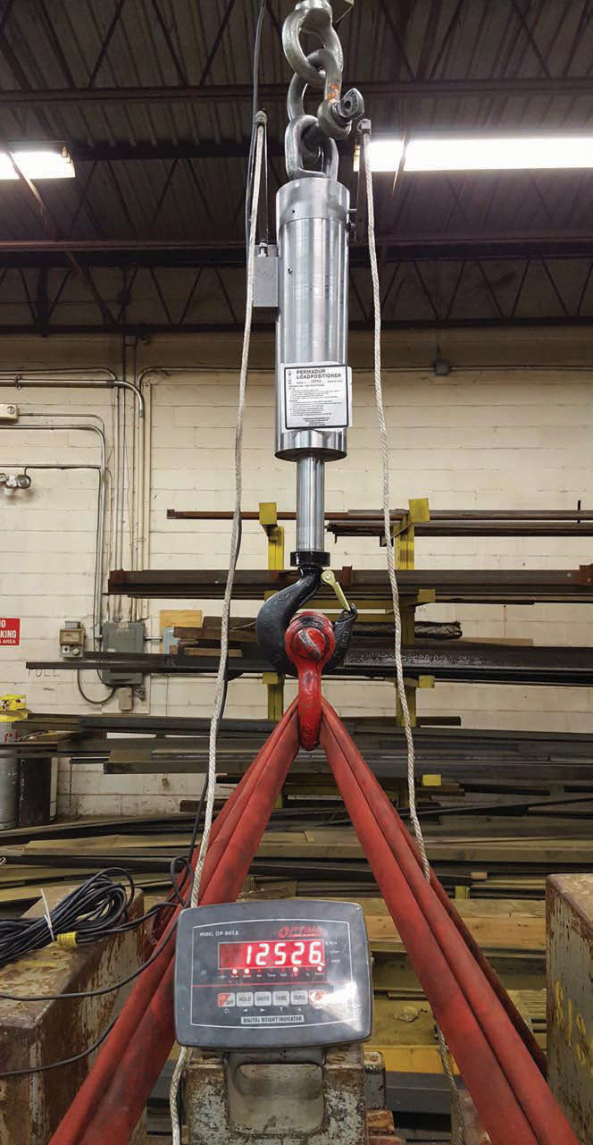
Permadur again has a unique belowthe- hook solution, in the form of its Hydraulic Load Positioning devices. They are designed to simplify alignment and assembly processes in many applications— “to precisely locate assemblies or component parts that just can’t be done by traditional means,” as Pavlosky puts it. The Load Positioner is a vertically arranged hydraulic piston and cylinder device, essentially a pump, that is engineered for precision operation. The cylinder itself hangs from the hook, with the load hung from the piston rod beneath it. The hoist positions the load as reasonably near as it can to the required height, and then stops. The Load Positioner then precisely controls the last critical part of the lift, lowering to the final position by a simple motion of the hydraulic pump.
The pump motion can be done manually or by remote control; a complete pump stroke moves the piston up or down by approximately 0.003–0.005 inches (0.07– 0.13mm) depending on the model; thus, the load is raised or lowered accordingly. An accuracy of .001 inches (0.025mm) is possible according to the manufacturer’s literature. It is available in an ‘L’ model, which has controlled metered lowering only, or in the ‘LL’ model which combines metered lifting and lowering in a single unit. They can be configured in standard hand-pumped hydraulic versions or using motorised actuators, with wireless radio controls when remote operation is necessary.
“We have customers who participate in the International Space Station Project and who use a plurality of these devices configured on a special lifting jig to lift, assemble and the control the positioning of a capsule or other rocket components on these projects,” says Pavlosky. “Aircraft maintenance providers use them to maintain alignment of jet engine components during servicing and assembly, and also when they dismantle them. Precision high-speed machinery makers such as horizontal centrifuge manufacturers also use them to assemble the very heavy component parts of their rotating assemblies. Even a local Space Exploration Laboratory has adapted them in a remote operation application to help maintain their telescope componentry. So you can see the flexibility of the applications just might be endless.” Another characteristic requirement of Industry 4.0 is data gathering and management. Below-the-hook vacuum lifters may not seem an obvious candidate to supply them; but Piab in January this year introduced what it says is a paradigm shift, the market’s first Industry 4.0-ready vacuum lifter, complete with internet connectivity. The piLIFT SMART, they say, senses and monitors movements, simultaneously lifts loads and weigh them, collects and logs the data, and sends the results though web platform log-in, for instantly-accessible statistical analysis.
Intended primarily for manual manipulators, and able to lift loads of 90lb (41kg) it could be attached also to hoists. “The capability of piLIFT SMART for collecting and analysing data to use for the optimisation of flows and processes is tremendous,” says David Collins, vice president and head of Piab’s Ergonomic Handling division.
Piab have also added broadened the scope of their Kenos KVG range of vacuum grippers. The range has been extended to include the option of using suction cups instead of the foam pads that are offered as standard. The suction cups are intended to better address materials or items that are otherwise particularly difficult to grip. Standard models use a replaceable foam pad that moulds itself around objects to provide a strong grip and seal regardless of the shape or dimensions. The number of holes, and the thickness of the foam, can be varied to suit different applications.
Suction cups offer advantages, says the company, in circumstances where the surface of the object might be wet or oily. Cups are available in flat-concave, bellows and long bellows shapes, and with long thin lips for good sealing on slightly corrugated surfaces such as corrugated cardboard. The cups are made from a specially-developed material that combines the elasticity of rubber with the wear resistance of polyurethane, which, says the company, makes them particularly suitable for uneven or porous surfaces.
Releasing a shackle while it is under load is not a usual procedure, but there are times when it is necessary. Emergency situations can demand it, which is why such devices have been available for yachtsmen as a way, for example, of releasing a squallhit sail quickly; but in the lifting industry they are less common.
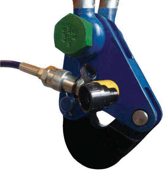
Durham Lifting have for several years manufactured quick-release shackles as special orders; they have now improved and patented the design and are refining the product for general release.
“It does not look like a conventional shackle, it’s more similar to a clamp,” says technical director Paul Gardiner. The release mechanism is hydraulic, with the hydraulic hose running down the umbilical. In most normal hydraulic shackles the pin is operated by the hydraulic actuator, which is hard to operate if the shackle is under load. “In the Durham design, we have bypassed the actuator pin taking the load,” says Gardiner. This means that the load is not directly applied to the pin of the hydraulic ram. Instead the actuator pulls a lever mechanism which releases the shackle. “It is a compact design, and part of the patent is concerned with reducing the size of the operating system.
“Applications for the quick-release shackle include both marine and onshore,” he says. “At sea it might be used for releasing and retrieving underwater RV vehicles, placing anti-scour mats and tidal turbine installation; it has previously been successfully used in applications at 45m tidal depth and excessive tidal conditions.”
Wind farms and tidal hydropower installations are the perfect applications for the shackle. The quick-release shackle was successfully used during the London Array windfarm project. This was a 175 turbine 630MW installation off the Kent coast and is the second largest offshore wind farm on earth.
“In wind farm applications, the quickrelease shackle is proven to increases operational health and safety,” adds Gardiner. The device can easily be released during zero visibility, in foggy conditions for example. Also, because the shackle is released remotely, it eliminates the need for the operator to be located on top of the tower in windy or excessive weather conditions. Capacities up to 150t are planned (ex stock), or larger if the demand is apparent. Some details are still confidential at time of writing. Durham Lifting are scheduled to release the shackle in the second quarter of 2019.