Designing for failure
27 September 2012This month Anupam’s contracts director B D Basu ruminates on the design parameters of single-failure-proof cranes intended for nuclear applications. Using a technical paper written in 1979, by Laurids Porse of the US Nuclear Regulatory Commission’s division of engineering standards, as his basis, Basu adds his thoughts on the key considerations
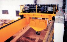
When nuclear power plant operators need to move heavy components such as spent fuel tanks and reactor vessel heads, the single failure proof (SFP) designed crane is the standard solution.
These loads are typically radioactive and require reliable, high-quality handling equipment to comply with the procedures in place for safe handling of critical loads. Various features related to design and construction of these cranes are described in this piece. Though it is predominantly used in the nuclear industry, the SFP crane can also be used in other sectors if the designers apply the right approach to incorporate these features.
For instance an SFP crane could be used in a chemical plant where the failure of a crane while lifting hazardous chemicals or highly explosive substances may jeopardise lives. Anupam Industries has supplied number of single failure proof cranes for nuclear power plant applications to the Nuclear Power Corporation of India (NPCIL) and Bhabha Atomic Research Centre (BARC), India.
Proper light-water reactor design specifies that all fuel storage and handling systems must ensure "adequate safety under normal and accidental conditions". One of the major concerns when designing this kind of crane is to feature safety parameters suitable for the loading factor.
Specification and design criteria of nuclear power application cranes
Depending on whether the crane is to be installed during the plant's construction or if it is destined for an operational plant, different performance parameters will have to be taken into consideration.
If the crane is installed after the construction period, certain changes to the crane system's design may be required. An initial consideration is that an adequately earthquake and radioactive proof bridge is designed so that the crane does not fail during such events while in permanent operating plant condition.
However if the crane is to be used during a plant's construction period, and any load lifts during construction are heavier than those required post-construction, then performance specification should include design criteria for a permanent crane for both periods.
Allowable desirable stress relief for cranes intended for plant operation should be as specified by Crane Manufacturers Association of America (CMAA) guidance. Anupam has developed a number of such cranes in the last couple of years compliant with CMAA standards.
Maximum critical load
Although the primary concern when designing a single failure proof crane must be its ability to handle the maximum critical load, it is better to design a crane with a design load that is slightly higher than this. With a capacity 10 per cent to 15 per cent higher than the maximum critical load, the effect of wear and exposure on important components can be offset.
This extra margin allows the crane to sustain its load handling capabilities during operation for longer before it drops below the maximum critical load.
An additional benefit of this is that in some cases, for instance during maintenance periods, SFP cranes may be used for lifting non-critical loads that are heavier than the maximum critical load rating. For non-critical loads such as these the design rated load rating should be used, even if certain crane components are required to be designed to maximum critical load rating.
Operating environment
A single failure proof crane should be in a position to withstand the maximum rate of pressure increase, temperature, humidity and emergency corrosive or hazardous conditions. This must be specified very clearly so that the crane fabricator is able to take this into account during the design of the crane.
The construction of the girder should be designed in such a way so that it is capable of venting out and avoiding collapse during containment pressurisation. This is the main reason that drainage is also provided, to avoid any water retention in the crane structure box section during its construction.
Material properties
Single failure proof cranes are generally fabricated from structural plates rolled from carbon steel. Alloying elements are not added except for 1 per cent manganese, which is added for heavier structures.
Some of the steel parts exceed 12mm in thickness, and in these cases toughness tests should be performed to ensure the crane can withstand rigorous operation.
The operating temperature should also be anticipated during testing. The minimum operating temperature must be clearly specified in order to lower the risk of brittle fractures of the ferritic load-carrying members of the crane.
Vital structural elements should also be impact tested to ensure adequate resistance to brittle fractures using either the ASTM E208 drop weight test, or a Charpy test as specified by ASTM A370.
The minimum operating temperature should then be obtained using the procedures detailed in paragraph NC-2300 or paragraph ND-2300 in Section III of the ASME code for the drop weight or Charpy tests respectively.
Seismic design
In the event of an earthquake during crane operations a well-designed SFP crane should still be able to retain control of the load, while the bridge and trolley remain firmly on their respective runways with the wheels prevented from leaving the tracks. During such an event equivalent to a safe shutdown earthquake, both the bridge and trolley should be able to stay on their runways with brakes applied.
SFP cranes should be designed and constructed in accordance with regulatory guidelines for seismic design calculation. To achieve this, the maximum critical load plus the operational and seismically induced pendulum and swinging load's effects on the crane must be taken into account for design of the trolley. This means that these loadings must also be allowed for when determining the trolley weight for the purpose of bridge design.
Bridge and trolley structure
As bridge and trolley structures are fabricated through the welding of structural shapes, manufacturers occasionally discover problems with weld joints between rolled structural elements due to subsurface lamellar tearing.
Although this can occur with the low joints during fabrication, lamellar tearing should not occur at all. These weld joints must be passed through radiographic and ultrasonic inspection as a matter of course.
An SFP crane's loading cycle will invariably produce cyclic stress. Also, for a crane used during a nuclear plant's construction period, additional cycles will contribute to the level of metal fatigue experienced. An evaluation to determine the likelihood of failure through fatigue should consider all of these factors.
When low-alloy steels are used for crane fabrication, difficulties can arise during welding or the post-welding heat treatment process if the base metal temperature is not carefully controlled. Both the pre-heat temperatures and post-welding heat treatment temperatures should be discussed, with a welding procedure determined through consultation between the manufacturer and the buyer.
All weldments should be made as recommended by the American Welding Society's (AWS) Structural Welding Code.
Safety features
For the purpose of single failure proof design, the crane handling system refers to all structural, mechanical and electrical components required to transfer a load from one place to another.
Load bearing components, equipment and subsystems such as the driving equipment, drum, rope reeving system, hooks, blocks, control systems and braking systems all need special design attention.
All mechanisms of any auxiliary hoist system on an single failure proof crane used to handle or assist handling of critical loads must also be single failure proof.
Auxiliary systems or dual components should also be provided for the main hoisting mechanism to guard against any failure of a component or subsystem that could jeopardise the crane's ability to support the load.
Provisions should be made and subsystems improved to prevent the accidental release of radioactive material in the event of a failure malfunction or loss of the load. Even in the event of a failure involving accidental operation or failure of the crane's subsystem control functions or components, the crane should be capable of stopping and holding the load. The system should also include an emergency stop button.
Design features enabling manual control through emergency devices of the hoisting system, bridge and trolley transfer mechanisms - in the event of crane immobilisation following component or control system failure or malfunction - should be included. This allows the crane to set down or continue supporting the load while repairs are made.
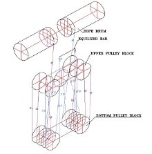
Reeving system and wire rope protection
The rope reeving system for a single failure proof crane needs special consideration during its design. Incorrect pitch diameter selection for the sheaves or choosing the wrong rope diameter can lead to excessive wearing of the rope.
Sheave pitch diameter should be larger when the load-carrying rope reaches its fastest speed near the drum, but can be smaller for sheaves used as equalisers when the rope is stationary.
Incorrect alignment of the load-carrying rope or inappropriately large fleet angles can also cause excessive wear, as the rope will rub against the sides of grooves in the drum and sheaves. This wear can be exacerbated if the load-carrying rope is partly held by friction on the groove wall, and so conservative fleet angles should used with special care taken during alignment of the rope.
Design of the rope reeving system should be dual with each system providing, separately, the load balance on the head and load blocks through the configuration of the rope and rope equaliser.
The maximum fleet angle from drum to lead sheave in the main block or between individual sheaves should not exceed 3.5 degrees. The use of reverse bends for running wire rope should be limited and larger sheaves should be used for this application. A reverse bend is a configuration of two sheaves each providing 1.57 rad (90 degree) wire rope bends, with the two adjacent planes of bending intersecting at an angle greater than 2.09 rad (120 degrees). Two successive bends in the same direction, the same plane, and not reversed have an angle of zero degrees. Two bends in directions in the same plane (reverse bend) have an angle of 3.14 rad (180 degrees).
The equaliser for stretch and load on the rope reeving system may be from an equaliser beam or heave, or a combination of the two.
A dual rope reeving system has individual attaching points to balance or distribute the load between two operating rope reeving systems. This guards against excessive shock in the event of a failure of one of the rope systems, allowing the remaining functional system to support the critical load.
The pitch diameter of the running sheaves and drums should be selected as specified in the CMAA's recommendations.
If lifts occurring at angles significantly different from those expected during a normal vertical lift are unavoidable, side loading can cause additional wear on the sheaves and wire rope.
In such instances the reeving system should be equipped with a guard to secure the rope in position and prevent it from being damaged by side loads or track loading, which could cut the rope if it jumps its groove barrier on the drum.
Drum support
To ensure the load hoisting drum on the trolley does not disengage from the holding brake system during a permanent failure of the drum shaft or bearings, structural and mechanical safety devices should be employed to limit the fall of the drum.
The head and load blocks are also to be designed in an approriate manner, in accordance with this reeving system.
Trolley, bridge and hoist braking systems
Braking systems provide another important function for the single failure proof crane for both the hoisting and lowering of critical loads.
Mechanical holding brakes in the hoisting system should be automatically activated when electric power is shut off or power is tripped for any reason.
This activation is triggered through an overload device or an over-speed device in the hoisting system, which will apply braking to achieve the full holding position when a malfunction occurs. Care must be taken to ensure the holding brake can achieve full stopping capacity while not having excessive stopping capacity that causes additional damage in the event of a failure of the crane system.
A minimum brake capacity of 125 per cent of the torque developed through hoisting operations must be considered during design.
The minimum specification for a hoist braking system used on a single failure proof crane should include one power control braking system and two holding brakes. The power control braking system should not be a mechanical brake or drag type brake.
The holding braking system must also be of single failure proof design, meaning that any component or gear train should feature redundancy via dual components, if interposed between the holding brakes and the hoisting drum.
In addition, both bridge and trolley systems should be equipped with control and holding brake systems that automatically apply during a power failure, overload or other malfunction in the drive system to avoid uncontrolled incidents.
Limiting devices, mechanical and/or electrical, should be provided to control or prevent over-travel and overspeeding of the trolley and bridge.
Rubber or spring loaded buffers for bridge and trolley travel should be included at the end of the rails.
Safety devices such as limit-type switches should also be provided to prevent malfunctions of the crane, in addition to guarding against user errors initiated by the crane operator.
Anupam has supplied these types of cranes, designed with two motors and also with a single motor design, as required by the client. A comparison between these two designs is given below in the table 'single motor design comparison to dual motor design' on the previous page.
Nuclear overview of India
The development of new nuclear power plants is the only solution to overcome the current global shortfall in power generation capacity, particularly in developing countries. France currently produces more of its domestic energy requirement through nuclear power than any other country in the world.
Considering today's power situation in India, we have to gear up our nuclear activity to offset the shortage of power in many parts of the country. India needs to establish more nuclear plants across different states in the days to come, and as a result demand for single failure proof cranes will certainly increase.
But the most pressing current concern is to produce cranes with high quality and workmanship to suit the stringent requirements of nuclear regulation.
Present nuclear power capacity is in India is around 4780MW. The countries mentioned above are the dominating nuclear power producers. India's presence is negligible. A concentrated approach is being envisaged by the government of India and private companies to augment present capacity and emerge as one of the leading producers of nuclear power in the world. To our knowledge, as a dominant crane manufacturer, India's present share of global nuclear power generating capacity is 3.7 per cent, and I expect this will increase by at least 10-15 per cent. As a result single failure proof cranes are in growing demand for this growing sector.
Single failure proof cranes are tested as per the IS-3177 standard in domestic markets, but they can also be tested as per CMAA standards for overseas markets.
The following checks must be performed
1) The first checks require testing to be carried out as per recommendations in the design specification.
a) Measurement of critical dimensions and verification with respect to GA drawing.
b) No load run for all motions and measurement of speed and current drawn by respective motor in the no-load condition.
c) Watching movement for all three types of speed in safe working load (SWL) condition. Also, measurement of speed and current in SWL condition.
d) Measurement of deflection of both girders in SWL condition.
e) Watching hoisting, cross travel and long travel movement at 125 per cent of SWL overload condition.
f) Confirm that there is no permanent set in girder structure.
2. Apart from these routine tests, some other tests have to be carried out to ensure that the crane is capable of lifting the standard working load with each path to the wire rope. To confirm this, the following tests should be carried out.
a) Carry out the rope reeving for the first path of wire rope.
b) Conduct load testing with this path of wire rope. This will ensure that this particular path of wire rope is capable of lifting the specified load.
c) Now detach this rope reeving as done at point a) above.
d) Carry out wire rope reeving for another path of wire rope.
e) Conduct load testing to the standard working load with this path of wire rope. This will ensure that the second path of wire rope is also capable of lifting the specified load.
f) Finally, carry out wire rope reeving for both paths, then lift the specified load. This will ensure that both the paths are jointly capable of smoothly lifting the specified load without any hinderance.
3. An optional test may be carried out to ensure one particular path of wire rope can support the load even if there is some damage to, or a failure in the second path of rope reeving. This test should only be carried out jointly by both the manufacturer and buyer. If this test needs to be done, it can be done in following sequences.
a) Carry out wire rope reeving of both paths. Lift the standard working load in this condition. Once this has been done, one of the wire rope paths should be detached from the system. This method of detaching wire rope may be carried out with some additional fixtures, and if you intend on doing this it should be planned in advance.
b) Similarly, load tests can be carried out to ensure that the second path for the hoisting system is capable of maintaining the load in a lifted position even if the other path malfunctions. For this the standard working load should be lifted, and the other system should be detached from the complete lifting system by additional fixtures as mentioned in point a) above. However, this test must be carried out with the utmost care to ensure safety for the workers and for the safety of the equipment itself. The method for detaching one particular wire rope path should be planned to avoid any hazard or risk of injury to anyone working and the equipment itself.