Aligning overhead crane rails
17 January 2008John C Wickhart of Washington DC has applied for international and US patents for a method and apparatus for performing alignment surveys on overhead cranes.
Summary
The survey apparatus of the invention is alternately pushed or pulled by the travelling crane. It consists of a wheeled carriage including survey sighting targets, such as prisms, that are visible to survey personnel standing on the ground. Using conventional survey instruments, data is collected for X, Y and Z coordinates to generate, as required, a rail alignment profile, a rail elevation profile, a rail span profile and a crane skew profile. These profiles can be used to determine whether the crane confirms to alignment specifications. The skew data can also be used to determine whether the crane itself may be misaligned.
Previous art
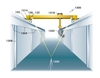
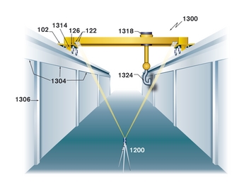
The apparatus of the invention is designed to work with a typical overhead crane in which the crane spans a distance between two crane rails (Fig 1 - 1302) with each rail supported by girder which is, in turn, supported by a series of columns. The crane contacts each of the crane rails with an end truck with two or more wheels (1316) at each end. The leading and trailing ends of each end truck are terminated with a rail sweep (1314).

Typically the crane includes a trolley (Fig 4 - 1318) travelling between the two end trucks on a pair of bridge rails, each with a bridge girder support. The trolley will carry hoisting mechanisms and load hooks (1324). Thus, as is usual, the crane operator can move cargo between any two locations between the crane rails.
Due to the large scale of typical industrial overhead cranes and heavy loads, proper alignment of crane rails and crane wheels is crucial to safe and efficient operation. The invention cites alignment standards outlined in the Crane Manufacturers Association of America (CMAA)'s specification 70 and AISE technical report No 13.
Many types of conventional rail surveys involve time-consuming methods requiring the rail to be locked out (turning off the power to the hot rail), with survey personnel walking the length of the runway.

As well as alignment other important factors include the positioning of the crane end-truck wheels parallel to their respective crane rails, and/or assuring that the drive motor output provided to the respective end-trucks is equivalent. Imbalances in the drive motor output can cause crane skew even if the rail alignment is within tolerances. Excess wear and tear on the rail and crane wheels will result requiring expensive repairs. Thus a safe method for quick and accurate collection of rail survey data, to find the root cause of misalignment problems, would be very beneficial.
Previous methods may include use of piano wire for rail straightening, using a tape measure to check the span between the rails. This method is not very accurate and is very time consuming. More accurate is the use of setting a transit on the rail and stopping at various points to take readings by survey personnel, but measuring the span still involves use of a tape measure. Another instrument is required to check rail elevation.

The inventor cites two earlier patents that are dedicated to the needs of overhead cranes rather than train tracks. One US Patent (2005/011 1012 by Steven Waisanen, published May 26 2006) uses a self-levelling, remotely operated laser survey device as a stationery component, and a mobile component with a screen and image capture device. The laser emits a beam of light towards the screen of the mobile part as it travels the length of the crane rail. The image capture device collects the data of the position of the laser light beam on the target and transmits to a remote computer. This data is used to assess the alignment of the crane rail. Wickhart claims that Waisanen does not provide details of claimed alternate embodiments for crane rail configurations, but covers a bottom-running crane rail configuration.
US Patent Number 6,415,208 by Romauld Pojda, issued on July 2 2002, also describes a similar laser-based device but configured to collect data for top-rail crane configuration.
Waisanan claims that these two patented devices suffer from serious deficiencies including reliance on complex combinations of electronics, including mobile operation in harsh environments likely to result in failure and the need for specialised repairs. He also claims that these devices are not capable of providing sufficient information quickly and accurately to identify the cause of misalignment problems (on rail alignment information only in these cases, with nothing on span alignment and elevation), and are incapable of giving timely information on crane skew to identify and correct imbalances in the drive motors.
Total station
A typical total station (ET/EDM) (Fig 8 -1200) is used in conjunction with the rail survey carriage. It is mounted on a tripod with a calculator attached including a keypad and display, and is used to determine angles and distances to the points being surveyed, thus allowing the coordinates of these positions to be calculated by trigonometry. This data can be downloaded to a computer and application software used to generate a map of the surveyed area. The total station may also have a GPS interface.
The total station generates angle results as digital read-outs, being more accurate and less prone to errors due to interpolating between scale marks and any misrecording. Readouts are also continuous so angles can be reviewed at any time. The use of reflecting prisms also improves accuracy in the laser EDM. If a data recorder is used for downloading measurement data and target location codes it can also reduce the potential for error.
When first switched on the total station may set itself to zero degrees (north), but a control knob will allow this siting to be reoriented by rotating the whole instrument. Thus in this way the total station, or ET/EDM, can be used in conjunction with the rail survey carriage to perform surveys of the crane.
Rail survey carriage
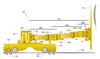
In Fig 1 a form of rail survey carriage (100) is shown in side elevation attached to a crane rail sweep. Included is an end rail bumper (1310) acting as a collision damping mechanism in case the crane exceeds its designed operating zone along the crane rails. This bumper can also be used as support for a carriage safety harness (1311) to prevent the rail survey carriage from falling down.
Fig 2 shows an enlargement of Fig 1 showing the rail survey carriage with a body (102) that rides on the crane rail via survey carriage wheels (104). The carriage is connected to the rail sweep via a swivel arm (106), or drive arm, allowing the survey carriage to be moved selectively along the rail. The swivel am is connected to the survey carriage body via a pivot post (108) extending from a survey carriage hinge (110) and connected to the body by a hinge pin (111). A force applied from the crane rail sweep to the survey carriage pivot post is dampened by a survey carriage hinge spring (112). At the other end the swivel arm is attached to the rail sweep via a bracket (120) above the crane rail.
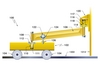
The rail survey carriage includes a prism arm (126), extending in a direction generally perpendicular to the crane rail, towards the opposite crane rail. At least one prism (122) is attached via a bracket (124) to the of the prism arm. Additional prisms can be attached to facilitate sighting of at least one of the prisms by the total station.
The prism arm may also include prism arm counterweights on the opposite end of the prism arm to where the prisms are mounted. Connections may be bolted. The counterweights are selected to counterbalance the combined weight of the prisms and prism arm. The combined weight of the assembly is therefore centred over the centreline of the survey carriage body extending in a direction parallel to the length of the crane rail.
The sighting target on the prism arm is mounted at a known offset relative to the centreline of the survey carriage body.
The patent includes a detailed description of the components of the first example of a rail survey carriage and an ‘exploded’ diagram of these components. Component features include outer circumferential flanges (105) on the survey carriage wheels. The wheels may be tapered to aid centring of each survey carriage wheel pair, and hence the carriage body, on the crane rail.
Fig 3 shows a second example of a rail survey carriage in schematic side elevation with several modifications. These include single survey carriage wheels positioned at each end of the carriage body attached by a single axle. The wheel rides directly on top of the crane rail. To ensure that the carriage remains aligned with the centreline of the crane rail, the survey carriage includes carriage stabilising side-arms each with a stabilising wheel. Suggested wheel material is polyurethane with a Shore Scale 9OA. The stabilising wheels make tight contact with the side faces of the crane rail to ensure centring. Each rotates about an axis to reduce friction and wear.
Another modification is the construction of the survey carriage swivel arm or drive arm. It includes several rigid members connected together at one of more adjustable joints allowing adjustment of the angles at the time of installation, for example sections 206A, B and C in the diagram. The adjustable joints are formed about a central hole (243) with several circumferential holes (245) in one member being connected and circumferential slots (247) formed in the rigid plates of the other member being connected. With bolt connection this allows the members to be rotated relative to each other to achieve the desired angle.